


PPP-IPCP Chassis Management Channel 163
Models 2616RC, 3096RC & 3196RC Admin Reference Guide 11 • In-band management
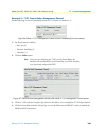
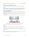
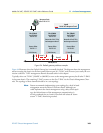
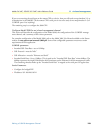
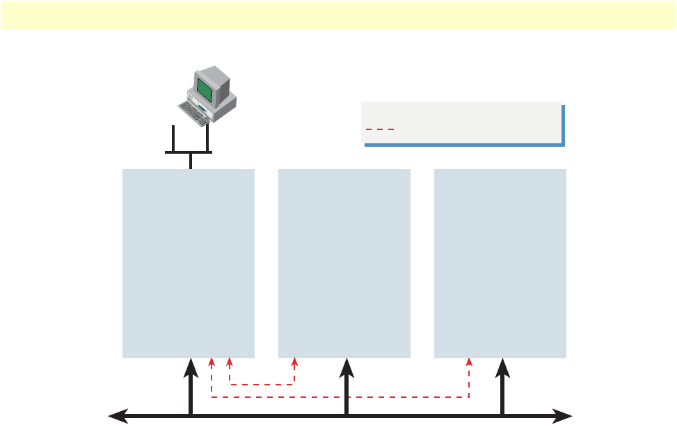
Figure 94. Default gateway address example
Figure 94 illustrates when the Default Gateway box is normally checked. The diagram shows the management
station accessing the chassis via the front panel Ethernet port of a T-DAC card, however just as easily the con-
nection could be a T1/E1 management channel discussed earlier in this chapter.
Typically, select one T-DAC (3196RC or 3096RC) to serve as the management gateway for all other T-DACs
in the same chassis. The remaining T-DACs connect to the first T-DAC via the Chassis Management Chan-
nels. The topology of these channels should be in a star topology.
Note
Patton recommends implementing a star topology for a local in-band
management network within a ForeFront chassis. Although you
could implement the chassis management using a daisy-chain topol-
ogy, the fault-tolerance of the management communication is
severely weakened due to a break in one link will isolate all “down-
stream” T-DACs from being reached.
Slot 4 (Node)
Local IP Address
198.162.10.3
Gateway Address
198.162.11.1
Local IP Address
198.162.10.4
Gateway Address
198.162.10.3
Legend
Defined Chassis Management Channel
TDM Mid-plane bus
Slot 5 (Node)
Local IP Address
198.162.10.5
Gateway Address
198.162.10.3
Slot 3 (Root)
Default Gateway
F
Default Gateway
✔
F
Default Gateway
✔F
Remote side of the H.110 in-
band management channel 1
Remote side of the H.110 in-
band management channel 2
Channel 2
Channel 1
Management Station
Address 198.162.11.1