


DLMI window 97
Models 2616RC, 3096RC & 3196RC Admin Reference Guide 8 • Frame Relay
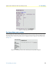
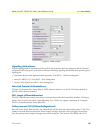
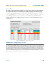
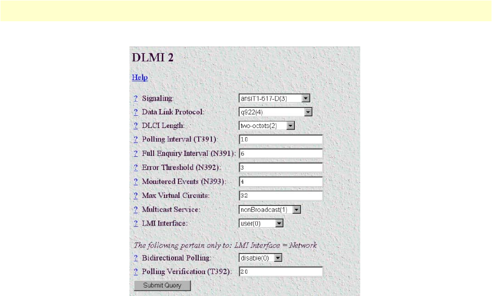
Figure 37. DLMI window
Signalling (frDlcmiState)
Inband signalling used to communicate link and PVC status between the User equipment and the Network
equipment. LMI is the generic term used to indicate Frame Relay signaling, however the three specific types of
signaling are:
• LMI Frame Relay Forum Implementation agreement. Uses DLCI = 1023 for management
• Annex D. ANSI T1.617 Uses DLCI = 0 for management
• Annex A. ITU Q.933 Uses DLCI = 0 for management
Data Link Protocol (frDlcmiAddress)
The layer 2 link protocol for Frame Relay is LAPF, otherwise referred to as Q.922. The factory default of
q922(4) will be the most common.
DLCI Length (frDlcmiAddressLen)
The DLCI identifies the virtual connection on the bearer channel for the Frame Relay Interface. The factory
setting of two-octets(2) represents 10-bit addressing. Your T-DAC can support a maximum of 32 separate
PVCs or virtual channels per Frame Relay link.
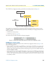
Polling Interval (T391)(frDlcmiPollingInterval)
Each side of the Frame Relay interface, the Network side and the User side, communicate status. T391 is the
number of seconds between subsequent Status Enquiry messages. An Error Count is logged if no response
from the previous Status Enquiry message was received during the T391 interval. The default value is 10.