


Defining a G.SHDSL Management Channel 167
Models 2616RC, 3096RC & 3196RC Admin Reference Guide 11 • In-band management
The Model 2616RC makes the T1/E1 Management Channel to the “outside” world, such as the NOC, as the
default gateway. The previous section for T1/E1 in-band management channels in this chapter describes the
configuration for this type of management connection.
The 3096RC has its management connection via the chassis management channel, so its default gateway is
automatically added to the routing table because we checked the Default Gateway box upon defining the man-
agement channel.
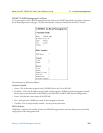
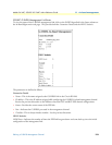
Defining a G.SHDSL Management Channel
The management channel may also be over a G.SHDSL link on a 3096RC T-DAC. Once the link has been
established, the user can configure, monitor, upgrade software and download/upload configuration files of the
ForeFront chassis cards.
Note
This link is intended for management purposes only, the link should
not be used as a router.
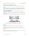
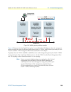
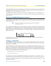
You can choose any G.SHDSL port for in-band management. Timeslot 1 is always used for carrying the man-
agement traffic. The remaining timeslots may be used for normal data traffic, if desired. The CPE would be a
Patton 3086 IAD. The single timeslot terminates on the 3086’s Ethernet port. The remaining timeslots will be
mapped to the serial port of the 3086, which may carry normal data traffic. The Ethernet port will carry man-
agement traffic only.
The CPE must operate over HDLC with the WAN service configured for either a routed PPP (IPCP) or a
bridged PPP (BCP) connection.
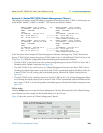
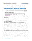
IP Addresses—IPCP & BCP
On the 3096RC, the IP address is dependent upon the management link being IPCP or BCP. When config-
ured for IPCP, the IP address is that of the remote peer, the CPE. For BCP, the IP address is assigned to the
local interface on the 3096RC.
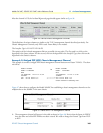
The BCP link operates as a HALF bridge, indicating that the 3096RC terminates the BCP link with a routed
interface. This will behave like an additional Ethernet port on the 3096RC. The IP address assigned to the
BCP connection should be on a separate subnet from the Ethernet subnet. The exception to this rule is when
the BCP subnet is configured as a portion of the Ethernet subnet. In this case, the 3096RC will proxy-ARP for
addresses on each side of the link. See the following example.
3096RC Ethernet IP:192.168.200.10/24
BCP IP:192.168.200.17/29
This configuration explicitly tells the 3096RC that the addresses 192.168.200.16 – 192.168.200.23 exist on
the BCP interface instead of the Ethernet interface. The 3096 will respond to any ARP request it receives on
the Ethernet interface for this address list. The traffic will then be routed to the address on the BCP side. This
will simulate a full bridge.
Time
Slot 1:
ENET
2 3
Remaining time slots for serial port of CPE, if needed
• • •
n - 1 n