


DS0 Fallback Configuration window 63
Models 2616RC, 3096RC & 3196RC Admin Reference Guide 5 • DS0 Mapping
To define value for the time slots parameter, you will enter a text string specifying which time slot numbers will
be used for the channel. You must enter the text string using a prescribed notation comprised of the following
elements:
• Numerals—Use numerals (1, 2, 3, 4, 5, 6, 7, 8, 9) to represent time slot numbers
• Comma—Use the comma (,) to separate non-contiguous timeslots. For example, the string 1,7,15 repre-
sents three timeslots numbered 1, 7 and 15.
Note
You may also use the comma to separate contiguous timeslots. How-
ever, since it is inefficient and may be confusing, doing so is not rec-
ommended.
• Dash—Use the dash ( - ) to represent a series of contiguous timeslots. For example, the string 1–32 repre-
sents all timeslots between 1 and 32 inclusive (i.e. time slot 1, time slot 32 and all time slots in between).
Slot Numbering Examples. For example, to define a channel comprising timeslots 1, 2, 5, 6, 7, and 15, either
of the following entries would be valid.
• 1,2,5-7,15
• 1-2,5-7,15
Note
Do not insert spaces after the commas.
Although the first string above is valid syntax, the second string is easier to read, and more clearly shows what is
going on.
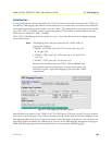
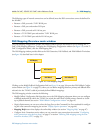
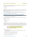
In case of failure, switch to the following port
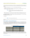
The In case of failure, switch to the following port section parameters (see figure 19 on page 58) define the alter-
nate (backup) channel in a fallback mapping. If the fallback channel comprises a T1/E1 or DSL port (i.e. not
an H.110 connection), you must define the first fallback port only, (i.e. the first three parameters) as shown in
table 3. When the fallback channel comprises an H.110 connection, you must define both fallback ports (i.e.
all six parameters) as shown in table 3.
The first set of fallback port parameters (Fallback Port Type, Fallback Port Number, and Fallback Port Slots)
defines the transmit connection to the H.100 bus from the T-DAC. The second set of fallback port parameters
defines the receive connection from the H.110 bus to the T-DAC. The following sections describe the fallback
channel parameters.
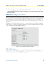
Table 3. Fallback port configuration
T1/E1 or DSL port H.110 port
Fallback Port Type Configure Configure
Fallback Port Number Configure Configure
Fallback Port Slots Configure Configure
Fallback Port Type Configure
Fallback Port Number Configure
Fallback Port Slots Configure