128
4.3 Typical Configuration Examples
1/7 1/9
1/11
1/5
PC1
MAC:00-01-11-11-11-11
PC4
MAC:00-01-44-44-44-44
PC3
MAC:00-01-33-33-33-33
PC2
MAC:00-01-22-22-22-22
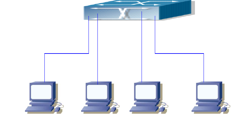
Fig 4-2 MAC Table typical configuration example
Scenario: Four PCs as shown in the above figure connect to port 1/5, 1/7, 1/9, 1/11 of
switch, all the four PCs belong to the default VLAN1. As required by the network
environment, dynamic learning is enabled. PC1 holds sensitive data and can not be
accessed by any other PC that is in another physical segment; PC2 and PC3 have static
mapping set to port 7 and port 9, respectively.
The configuration steps are listed below:
1. Set the MAC address 00-01-11-11-11-11 of PC1 as a filter address.
Switch(Config)# mac-address-table static 00-01-11-11-11-11 discard vlan 12. Set the
static mapping relationship for PC2 and PC3 to port 7 and port 9, respectively.
Switch(Config)# mac-address-table static 00-01-22-22-22-22 interface ethernet 1/7 vlan 1
Switch(Config)#mac-address-table static 00-01-33-33-33-33 interface ethernet 1/9 vlan 1
4.4 Troubleshooting Help
4.4.1 Monitor and Debug Commands
4.4.1.1 show mac-address-table


