


417
15.4.3 Typical OSPF Scenario
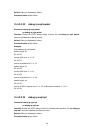
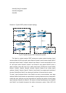
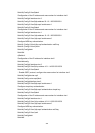
Scenario 1: OSPF autonomous system.
This scenario takes an OSPF autonomous system consists of five ES4626/ES4650
layer3 switches for example, where layer3 switch Switch1 and Switch5 make up OSPF
area 0, layer3 switch Switch2 and Switch3 form OSPF area 1 (assume vlan1 interface of
layer3 switch Switch1 belongs to area 0), layer3 switch Switch4 forms OSPF area2
(assume vlan2 interface of layer3 Switch5 belongs to area 0). Swtich1 and Switch5 are
backbone layer3 switches, Swtich2 and Switch4 are area edge layer3 switches, and
Switch3 is the in-area layer3 switch.
SWI
T
Fig 15-3 Network topology of OSPF autonomous system.
The configuration for layer3 switch Switch1 and Switch5 is shown below:
Layer3 switch Switch1:
!Configuration of the IP address for interface vlan1
Switch1#config
Switch1(Config)# interface vlan 1
Switch1(Config-if-vlan1)# ip address 10.1.1.1 255.255.255.0
Switch1(Config-if-vlan1)#no shut-down
Switch1(Config-if-vlan1)#exit
! Configuration of the IP address for interface vlan2
Switch1(Config)# interface vlan 2
Switch1(Config-if-vlan2)# ip address 100.1.1.1 255.255.255.0
Switch1 (Config-if-vlan2)#exit
!Enable OSPF protocol, configure the area number for interface vlan1 and vlan2.
Switch1(Config)#router ospf
Switch1(Config-router-ospf)#exit
Switch1(Config)#interface vlan 1
Switch1 (Config-if-vlan1)#ip ospf enable area 0
Switch1 (Config-if-vlan1)#exit