288
Switch(dhcp-A-config)#dns-server 10.16.1.202
Switch(dhcp-A-config)#netbios-name-server 10.16.1.209
Switch(dhcp-A-config)#netbios-node-type H-node
Switch(dhcp-A-config)#exit
Switch(Config)#ip dhcp excluded-address 10.16.1.200 10.16.1.210
Switch(Config)#ip dhcp pool B
Switch(dhcp-B-config)#network 10.16.2.0 24
Switch(dhcp-B-config)#lease 1
Switch(dhcp-B-config)#default-route 10.16.2.200 10.16.2.201
Switch(dhcp-B-config)#dns-server 10.16.2.202
Switch(dhcp-B-config)#option 72 ip 10.16.2.209
Switch(dhcp-config)#exit
Switch(Config)#ip dhcp excluded-address 10.16.2.200 10.16.2.210
Switch(Config)#ip dhcp pool A1
Switch(dhcp-A1-config)#host 10.16.1.210
Switch(dhcp-A1-config)#hardware-address 00-03-22-23-dc-ab
Switch(dhcp-A1-config)# client-name management
Switch(dhcp-A1-config)#exit
Scenario 2:
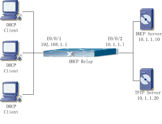
Fig 11-3 DHCP Relay Configuration
As shown in the above figure, route switch is configured as a DHCP relay. The DHCP
server address is 10.1.1.10, TFTP server address is 10.1.1.20, the configuration steps is
as follows:
Switch (Config)#service dhcp
Switch (Config)#interface vlan 1
Switch (Config-if-Vlan1)#ip address 192.168.1.1 255.255.255.0
Switch (Config-if-Vlan1)#exit


