


421
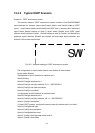
floods in area 1, those LSA are included in the area 1 database to get the routes to
network N11 and N15.
In addition, layer3 switch Switch3 and Switch4 must summary the topology of area 1 to
the backbone area (area 0, all non-0 areas must be connected via area 0, direct
connections are not allowed), and advertise the networks in area 1 (N1-N4) and the costs
from Switch3 and Switch4 to those networks. As the backbone area is required to keep
connected, there must be a virtual link between backbone layer3 switch Switch10 and
Switch11. The area edge layer3 switches exchange summary information via the
backbone layer3 switch, each area edge layer3 switch listens to the summary information
from the other edge layer3 switches.
Virtual link can not only maintain the connectivity of the backbone area, but also
strengthen the backbone area. For example, if the connection between backbone layer3
switch Switch8 and Switch10 is cut down, the backbone area will become discontinued.
The backbone area can become more robust by establishing a virtual link between
backbone layer3 switches Switch7 and Switch10. In addition, the virtual link between
Switch7 and Switch10 provide a short path from area 3 to layer3 switch Switch7.
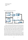
Take area 1 as an example. Assume the IP address of layer3 switch Switch1 is 10.1.1.1,
IP address of layer3 switch Switch2 interface VLAN2 is 10.1.1.2, IP address of layer3
switch Switch3 interface VLAN2 is 10.1.1.3, IP address of layer3 switch Switch4 interface
VLAN2 is 10.1.1.4. Switch1 is connecting to network N1 through Ethernet interface
VLAN1 (IP address 20.1.1.1); Switch2 is connecting to network N2 through Ethernet
interface VLAN1 (IP address 20.1.2.1); Switch3 is connecting to network N4 through
Ethernet interface VLAN3 (IP address 20.1.3.1). All the three addresses belong to area 1.
Switch3 is connecting to layer3 switch Switch6 through Ethernet interface VLAN1 (IP
address 10.1.5.1); Switch4 is connecting to layer3 switch Switch5 through Ethernet
interface VLAN1 (IP address 10.1.6.1); both two addresses belong to area 1. Simple
authentication is implemented among layer3 switches in area1, edge layer3 switches of
area 1 authenticate with the area 0 backbone layer3 switches by MD5 authentication.
The followings are just configurations for all layer3 switches in area 1, configurations for
layer3 switches of the other areas are omitted. The following are the configurations of
Switch1 Switch2.Switch3 and Switch4: :
1)Switch1:
!Configuration of the IP address for interface vlan2
Switch1#config
Switch1(Config)# interface vlan 2
Switch1(Config-If-Vlan2)# ip address 10.1.1.1 255.255.255.0
Switch1(Config-If-Vlan2)#exit
!Enable OSPF protocol, configure the area number for interface vlan2.
Switch1(Config)#router ospf
Switch1(Config-router-ospf)#exit
Switch1(Config)#interface vlan 2
Switch1(Config-If-Vlan2)#ip ospf enable area 1
!Configure simple key authentication.
Switch1(Config-If-Vlan2)#ip ospf authentication simple key