


187
SW4(Config-Vlan20)#exit
SW4(Config)#vlan 30
SW4(Config-Vlan30)#exit
SW4(Config)#vlan 40
SW4(Config-Vlan40)#exit
SW4(Config)#vlan 50
SW4(Config-Vlan50)#exit
SW4(Config)#spanning-tree mst configuration
SW4(Config-Mstp-Region)#name mstp
SW4(Config-Mstp-Region)#instance 3 vlan 20;30
SW4(Config-Mstp-Region)#instance 4 vlan 40;50
SW4(Config-Mstp-Region)#exit
SW4(Config)#interface e1/1-7
SW4(Config-Port-Range)#switchport mode trunk
SW4(Config-Port-Range)#exit
SW4(Config)#spanning-tree
SW4(Config)#spanning-tree mst 4 priority 0
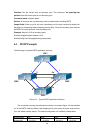
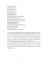
After the above configuration, SW1 is the root bridge of the instance 0 of the entire
network. In the MSTP region which SW2, SW3 and SW4 belong to, SW2 is the region root
of the instance 0, SW3 is the region root of the instance 3 and SW4 is the region root of
the instance 4. The traffic of VLAN 20 and VLAN 30 is sent through the topology of the
instance 3. The traffic of VLAN 40 and VLAN 50 is sent through the topology of the
instance 4. And the traffic of other VLANs is sent through the topology of the instance 0.
The port 1 in SW2 is the master port of the instance 3 and the instance 4.
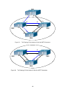
The MSTP calculation generates 3 topologies: the instance 0, the instance 3 and the
instance 4 (marked with blue lines). The ports with the mark “x” are in the status of
discarding. The other ports are the status of forwarding. Because the instance 3 and the
instance 4 are only valid in the MSTP region, the following figure only shows the topology
of the MSTP region.