


420
Switch5(Config-if-vlan3)#exit
Switch5(Config)#exit
Switch5#
Scenario 2: Typical OSPF protocol complex topology.
Do mai n 2Do mai n 3
Do mai n 1
N3
N1
N8
N5
N6
N9
N1 0
N4
N2
N1 5
N1 4
N7
N1 2
N1 3N1 1
Do mai n 0
SWITCH1
SWITCH2
SWITCH3
SWITCH4
SWITCH5
SWITCH6
SWITCH9
SWITCH12
SWITCH11 SWITCH10
SWITCH7
SWITCH8
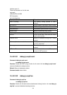
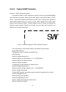
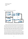
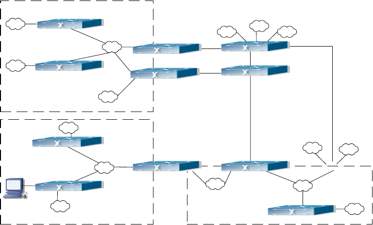
Fig 15-4 Typical complex OSPF autonomous system.
The figure is a typical complex OSPF autonomous system network topology. Area1
include network N1-N4 and layer3 switch Switch1-Switch4, area2 include network N5-N7
and layer3 switch Switch7, Switch8, Switch10 and Switch11, area3 include N8-N10, host
H1 and layer3 switch Switch9, Switch11 and Switch12, and network N8-N10 share a
same summary route with host H1(i.e. define area3 and a STUB area). Layer3 switch
Switch1, Switch2, Switch5, Switch6, Switch8, Switch9, Switch12 are in-area layer3
switches, Switch3, Switch4, Switch7, Switch10 and Switch11 are edge layer3 switches of
the area, Switch5 and Switch7 are edge layer3 switches of the autonomous system.
To area1, layer3 switches Switch1 and Switch2 are both in-area switches, area edge
switches Switch3 and Switch4 are responsible for reporting distance cost to all destination
outside the area, while they are also responsible for reporting the position of the AS edge
layer3 switches Switch5 and Switch7, AS exterior link-state advertisement from Switch5
and Switch7 are flooded throughout the whole autonomous system. When ASE LSA