


392
to be configured as STUB areas to reduce the topology database size. Type4 LSA (ASBR
summary LSA) and type5 LSA (AS exterior LSA) are not allowed to flood into/through
STUB areas. STUB areas must use the default routes, the layer3 switches on STUB area
edge advertise the default routes to STUB areas by summary LSA, those default routes
flood inside STUB only and will not get out of STUB area. Each STUB area has a
corresponding default route, the route from a STUB area to AS exterior destination must
rely on the defaulted route of that area.
The following outlines OSPF priority route calculation process:
1) Each OSPF-enabled layer3 switch maintains a database (LS database)
describing the link-state of the topology structure of the whole autonomous
system. Each layer3 switch generates a link-state advertisement according to its
surrounding network topology structure (router LSA), and sends the LSA to the
other layer3 switches through link-state update (LSU) packets. This way, each
layer3 switch receives LSAs from the other layer3 switches, and all LSAs
combined to the link-state database.
2) Since an LSA is a description to the network topology structure around a layer3
switch, the LS database is the description to the network topology structure of
the whole network. The layer3 switches can easily create a weighted vector map
according to the LS database. Obviously, all layer3 switches in the same
autonomous system will have the same network topology map.
3) Each layer3 switch uses the shortest path finding (SPF) algorithm to calculate a
tree of shortest path rooted by itself. The tree provides the route to all the nodes
in the autonomous system, leaf nodes consist of the exterior route information.
The exterior route can be marked by the layer3 switch broadcast it so that
additional information about the autonomous system can be recorded. As a
result, the route table of each layer3 switch is different.
OSPF protocol is developed by the IETF, the OSPF v2 widely used now is fulfilled
according to the content described in RFC2328.
15.4.2 OSPF Configuration
The OSPF configuration for the series switches may be different from the configuration
procedure to switches of the other manufacturers. It is a two-step process:
1. Enable OSPF in the Global Mode;
2. Configure OSPF area for the interface.
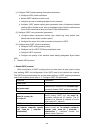
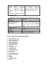
15.4.2.1 Configuration Task Sequence
1. Enable OSPF (required)
(1) Enable/disable OSPF (required)
(2) Configure the ID number of the layer3 switch running OSPF (optional)
(3) Configure the network scope for running OSPF (optional)
(4) Configure the area for the interface (required)
2. Configure OSPF sub-parameters (optional)