


1152700 • Issue 1 • February 2001 • Section 2 Operation and Maintenance
Page 2-152
2000, ADC Telecommunications, Inc.
DLP-728
Page 2 of 4
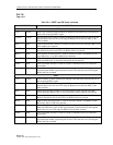
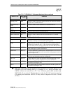
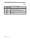
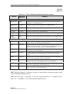
9. To configure the thresholds, place the cursor in the individual count boxes and type in the
new threshold value. Refer to Table 730-1 for valid values. Once all counts are entered in
each box, select the Apply button at the bottom of the screen to send the new data to the
database.
10. Select the Close button to dismiss the open windows.
Stop! You have completed this procedure.
Cellworx Vision: Performance Monitoring Selection Criteria
Close
X
Resource:
NE 1: Cellworx1
NE 2: Cellworx2
NE 4: CellworxEXP
Port Layer Interval
current
00:00 - 00:15
00:15 - 00:30
00:30 - 00:45
01:45 - 02:00
01:00 - 01:15
01:30 - 01:45
01:15 - 01:30
00:45 - 01:00
02:00 - 02:15
Apply
Slot / Card Type
Slot 7 / T3 CRS
Slot 10 / Port 1
Slot 10 / Port 2
NE 3: Cellworx3
Slot 10 / T3 CRS
Slot 10 / Port 3
PLCP
ATM/TC
Slot 4 / T1 MULTI 1
Slot 5 / E1 MULTI 1
Slot 6 / T3 TMUX MULTI
Slot 12 / 155 MM CRS
Slot 16 / 622 Ring
Slot 17 / 622 Ring
DS3
13562-B
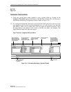
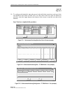
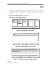
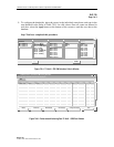
Figure 728-1.T3 CRS PM Selection Criteria Window
Cellworx Vision: Performance Monitoring Data NE 2
Card Type
X
T3CRS
Slot-Port Interval PESs PSESs SEFS UASs LCVs PCVs LESs CCVs CSESs
S10-P1 current
0 0 0 197 0 001970
DS3
Only non-zero selected intervals are displayed.
13558-B
Refresh All
Configure Thresholds
Close
Refresh Reset Selected Clear Selected
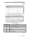
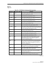
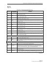
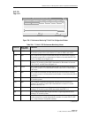
Figure 728-2. Performance Monitoring Data T3 Port Window
Cellworx Vision: PM Threshold Configuration DS3 Layer
Card Type
X
T3 CRS
Slot-Port PESs PSESs SEFSs UASs LCVs PCVs LESs CCVs
S10-P1
3 751060360 00
Close
Apply
13551-B
Figure 728-3. Performance Monitoring T3 Port Configuration Window