


1152700 • Issue 1 • February 2001 • Operation and Maintenance
Page 2-350
© 2000, ADC Telecommunications, Inc.
DLP-784
Page 1 of 7
SET FE1 FRS CARD CONFIGURATION
Summary: This procedure details the steps required to set the FE1 FRS card configurations
utilizing the Cellworx STN Phase 3.1 shelf level Graphical User Interface (GUI). User must have
the GUI launched, and have accessed the shelf level GUI display per NTP-006 prior to
performing this procedure.
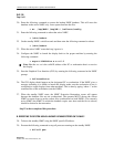
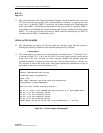
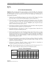
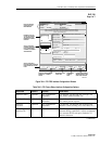
1. Double click on the FE1 FRS card displayed in the shelf level GUI “Chassis View”at the
top of the window. The FE1 FRS card display appears as shown in Figure 784-1.
2. Click and drag the small block upward to expand the Configuration section of the window
so all or most options are visible. The Administrative State of the card and port should be
“Unlocked” if in service. If “Locked”, select the “Unlocked” option using the left mouse
button to enable the card and/or port for service.
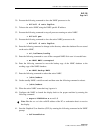
3. Set the Ingress and Egress Congestion Threshold for the switch fabric which will generate
an alert when the traffic congestion crosses the threshold set.
4. Set the Ring Selection to Auto, Ring 16, or Ring 17 as required. Refer to Table 784-2 for
definitions of all options selectable by the user.
5. Following the Ring Selection is the Smoothing Constant option. Click on the up or down
arrow to select from 0.1 to 1.0 in .1 increments. This value provides for exponential
smoothing for alarm notices that report/respond to congestion in the frame relay buffers. A
smaller number (0.1) will reduce chattering of alarm notices/clearings due to buffer
congestion during spikes in traffic.
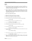
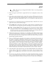
6. Following the Smoothing Constant settings is the Ingress and Egress, High and Low Buffer
Congestion Thresholds settings for the frame relay buffers. Refer to Figure 784-2 for
instructions on setting the thresholds.
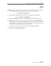
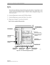
7. Following the Congestion Threshold settings, set the Port Mode for channelized or
fractional as required via the display shown in Figure 784-3.
Note: Selecting Channelized options will configure the card for four ports only (1, 2, 3,
and 4). Refer to Table 784-1 below for Port Level configuration options:
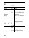
Table 784-1. FRS Port Configurations
MODE PORT
12345678
Channelized CH CH CH CH -- --
Fractional FRFRFRFRFRFRFRFR
Combinations CH CH FR FR FR FR
FR FR CH CH FR FR -- --