


1152700 • Issue 1 • February 2001 • Operation and Maintenance
Page 2-370
© 2000, ADC Telecommunications, Inc.
DLP-786
Page 7 of 10
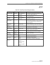
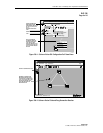
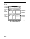
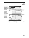
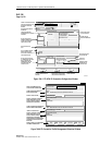
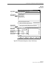
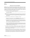
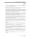
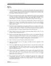
Cellworx Vision: Connection Configuration
X
Connection Name:
Connection Type: FR - FR
GNE-21 <--> RNE-22
Locked
Unlocked
GNE-21
RNE-22
RNE-23
Slot / Card Type:
Administrative State:
Network Element: NE-22
Network Interface / Interface Type:
ASSIGN A CONNECTION NAME
SELECT A CONNECTION
TYPE: VC,VP, FR, OR CES
SELECT AN NE FROM
AVAILABLE LIST FOR
ORIGINATING CONNECTION
ENDPOINT.
SELECT AN NE FROM
AVAILABLE LIST FOR
DESTINATION CONNECTION
ENDPOINT.
THE SLOT / CARD TYPE ARE
THEN DISPLAYED FOR
SELECTION HERE.
SELECT THE PORT AND
INTERFACE FROM AVAILABLE
LIST FOR THE ORIGINATING
CONNECTION ENDPOINT.
USE SLIDER BARS TO VIEW
MORE INTERFACES.
Network Element: NE-21
DS0-E0 FRS:Slot 13: Port 02: Cha
DS0-E0 FRS:Slot 13: Port 03: Cha
GNE-21
RNE-22
RNE-23
Slot / Card Type:
Network Interface / Interface Type:
Please select an endpoint 1 network element.
Endpoint 1
Endpoint 2
SELECT THE PORT AND
INTERFACE (FR) OR PORT
(ATM) FROM AVAILABLE
LIST FOR THE DESTINATION
CONNECTION ENDPOINT.
DS0-E0 FRS:Slot 12: Port 01: Cha
DS0-E0 FRS:Slot 12: Port 02: Cha
DS0-E0 FRS:Slot 12: Port 03: Cha
13 FE1 FRS
14 FE1 FRS
15 FT1 FRS
11 FE1 FRS
13 FT1 FRS
14 FT1 FRS
12 FE1 FRS
DS0-E0 FRS:Slot 13: Port 01: Cha
DS0-E0 FRS:Slot 13: Port 04: Cha
DS0-E0 FRS:Slot 12: Port 04: Cha
Next >>
Close
Apply
Refresh
THE SLOT / CARD TYPE ARE
THEN DISPLAYED FOR
SELECTION HERE.
0026-015
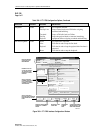
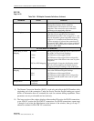
Figure 786-3. Connection Configuration Window