


1152700 • Issue 1 • February 2001 • Section 2 Operation and Maintenance
Page 2-192
2000, ADC Telecommunications, Inc.
DLP-738
Page 1 of 7
ADD A SECOND NETWORK ELEMENT
Summary: This procedure describes the steps required to add a second Cellworx STN node to
any existing in service stand-alone NE. The instructions provided by the Cellworx Vision
Graphical User Interface (GUI) should be followed precisely to minimize service impact on the
upgrade. It is assumed the user has already launched the GUI from the stand-alone node and the
required optics have been installed per NTP-004. Verify the correct shelf type setting has been
set per the Phase 3.1 Installation manual listed in the preface of this document.
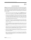
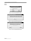
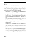
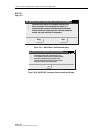
1. From the GUI screen, use the left mouse button to select the Configuration pull down
menu located above the workspace, and then Topology and Add Ring Network Element.
This can also be accomplished by entering Alt+C, Alt+N, and Alt+A. Refer to Figure 738-1.
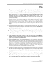
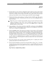
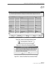
2. The Cellworx Vision: Add Second Ring NE - Task Overview window appears as shown in
Figure 738-2. The tasks that will be performed are listed in order from 1 to 8 with a pointer
indicating the current task. The first task is to enter the NE identifier as another window
appears as shown in Figure 738-3. Using the left mouse button, select the slider bar button
and move it to the right until the desired ID appears above the bar. In this example a 2 is
shown.
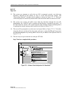
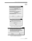
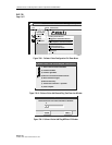
3. If an ID is entered that already exists, the message window shown in Figure 738-4 will
appear. Select OK and choose another number. Be sure the number selected is the same as
the number set on the node via the rotary switches on the protect SC TEIM card.
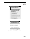
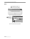
4. After making the ID selection, choose the Next button. The pointer on the Task Overview
window moves to step 2, Connect left RICs (cards in slot 16), and another window appears
as shown in Figure 738-5.
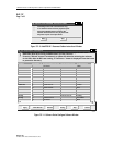
5. Follow the instructions for connecting the fibers between the RICs in the left slots of the
two nodes, and then select Next.
6. Another window similar to Figure 738-5 appears directing the user to connect the other set
of fibers between the RICs in the right slots of the two nodes (step 3 of the Task Overview).
Follow the instructions and select Next once completed.
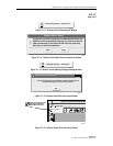
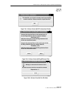
7. The Task Overview window now indicates that the system is waiting for the new network
element to boot (step 4 of the Task Overview) and an informational window appears as
shown in Figure 738-6. The NE should boot within sixty seconds. If the boot-up process
exceeds sixty seconds, another window prompts the user to retry or quit. Refer to Figure
738-7. Follow the instructions and select either Quit or Retry. If Quit is selected, the Add
NE - Reconnect Cables window appears. Refer to Figure 738-8. Follow the instruction to
return the equipment to its original physical state and select Quit, otherwise continue.