


1152700 • Issue 1 • February 2001 • Operation and Maintenance
Page 2-352
© 2000, ADC Telecommunications, Inc.
DLP-784
Page 3 of 7
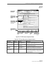
blue for the next channel(s) selected and the system will number it 2 and indicate it is the
“Current” channel. If multiple interfaces are displayed, the user must “double-click” on any
channel of the interface desired to make it “Current” to allow configuration changes or to
delete that interface.
16. Select the Close button to return to the FE1 FRS card display.
17. Select the Close button to return to the Chassis View window.
18. Repeat steps 1 through 17 for each card in the shelf.
Stop! You have completed this procedure.
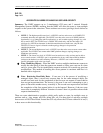
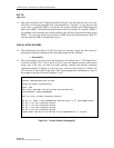
Cellworx Vision: Card View - E1 Frame Relay Service
Status:
Apply Chassis View
Refresh Close
X
Configuration:
Card Level
Administrative State: Congestion Thresholds:
Locked
Unlocked
Ingress:
Egress:
80
80
%
%
Port Level
Administrative State: Transmit Timing Source:
Locked
Unlocked
Recieved
Local
Line Build Out (LBO):
Line Coding:
Facility Line
Loopback:
Circuit Identifier:
default
NE Name: Cellworx1
NE Id: 20
Card: FE1 FRS
Slot Number: 13
Port Number: 1
Status
Active
APS
1
2
3
4
5
6
7
8
Port
ADC
FE1
FRS
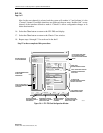
CLICK ON BOX AND DRAG
UP OR DOWN TO WIDEN
STATUS OR CONFIGURATION
VIEWS.
CLICK ON ANY PORT TO
CONFIGURE INDIVIDUAL
FE1 PORTS.
CLICK ON BOX AND DRAG UP
OR DOWN TO WIDEN PORT
LEVEL VIEW.
USE SLIDERS TO VIEW
HIDDEN SELECTIONS.
APPLIES CHANGES
AND SENDS TO SHELF
CONTROLLER.
RETURNS TO CHASSIS
VIEW WITHOUT CLOSING
CARD LEVEL VIEW.
REPAINTS WINDOW
TO REFLECT ANY
CHANGES.
CLOSES CARD LEVEL
VIEW AND RETURNS TO
SHELF LEVEL VIEW.
NE AND CARD TYPE/
SLOT INFORMATION.
CARD REPRESENTATION
WITH ALARM
INDICATIONS.
E1 PORT LEVEL
CONFIGURATION OPTIONS.
SELECT PORT FIRST.
CARD LEVEL
CONFIGURATION OPTIONS.
Ring Selection:
Auto Ring 16 Ring 17
120 Ohms
HDB3
Line Type:
E1 CRC-4 MF
Terminal
None
Facility Payload
Smoothing Constant:
0.3
0026-011
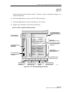
Figure 784-1. FE1 FRS Card Configuration Window