


1152700 • Issue 1 • February 2001 • Section 2 Operation and Maintenance
Page 2-243
© 2000, ADC Telecommunications, Inc.
DLP-753
Page 3 of 4
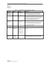
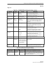
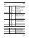
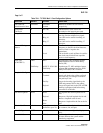
Table 753-1. T3 CRS Configuration Options, continued
SELECTION DEFAULT OPTIONS DEFINITIONS
Timing Port None None
Port 1
Port 2
Port 3
None does not provide timing when card slot is
selected, or uses Port 1, 2, or 3 for timing source
when slot is selected for system timing from
Timing Resource screen.
Line Type M23
M23
C-bit Parity
Asynchronous, M23 multiplex format, PM
parameters based on P-Bit Parity Errors (PE).
Synchronous T3, M13 multiplex format,
separate PM parameters based on P-Bit Parity
Errors (PE) CRC violations.
ATM Mapping Types Direct Direct
PLCP
HEC based “Direct” mapping.
Physical Layer Convergence Protocol mapping.
Transmit Timing Source Local Received
Local
The Tx clock (and data rate) is the same
frequency as the RX clock and data rate (receive
clock is looped to the transmitter).
The on-board crystal oscillator is used for the
clock source, so the transmit clock will be a
nominal 44.736 Mhz and will not equal the
receive clock frequency.
Line Build Out Off Off / On
Sets the signal level to compensate for the
distance between the system and the interfacing
equipment.
Loopback Config. None None
Terminal
Facility
Payload
No loopback activated on this card.
Sends cells back to the cellbus and back out to
the ring. No changes are made to the path layer.
Loops the incoming signal back to the CPE and
generates AIS to the cellbus.
Loops the signal back to the CPE AFTER
framing is performed and before being converted
to ATM cells.
Far End Loopback None Payload
Reset
Line
Determine the type of loop back at the far end to
test continuity between the far end and near end.
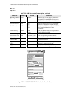
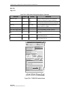
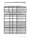
Table 753-2. ATM Interface Configuration Options
SELECTION DEFAULT OPTIONS DEFINITIONS
Interface Name Alphanumeric User defined, up to 20 alpha numeric characters.
Loopback Location Code All 1s Alphanumeric Used to loopback the incoming signal and
transmit it back to the customer equipment. The
code is limited to 16 numeric characters.
Recording Interface ID All 0s Numeric Identifies the site card and port location for
customer billing capabilities, (allows assignment
of a customer ID for each port.) The code is
limited to 15 numeric characters.
(continued)