


ADCP-70-220 • Issue 1 • September 2000 • Section 1 Introduction
Page 1-5
© 2000, ADC Telecommunications, Inc.
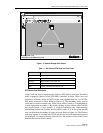
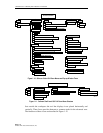
Cellworx Vision: Subnetwork Management System
File Configuration Fault Performance Help
GNE-1
NE-2
NE-3
10924-D
Cellworx User: root
Local Time: 21:35 GMT Time: 21:35
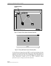
Figure 1-4. Network Manager Main Screen
Table 1-1. GUI Cellworx STN Node Icon Color Codes
COLOR INDICATION
Green No existing alarms, normal operation.
Yellow Minor alarms exist at this site.
Orange Major alarms exist at this site.
Red Critical alarms exist at this site.
Blue Cannot communicate with the site.
GUI Screen Icon Definitions
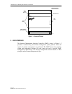
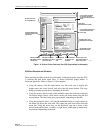
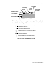
Larger icons are used to represent the Cellworx STN shelves that have Secondary
nodes (expansion shelves called STN-EPS) connected to them. These icons are
referred to as Primary nodes and will look the same whether there are 2 or 10 STN-
EPS nodes connected to them. Refer to Figure 1-5. The Secondary nodes may be
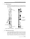
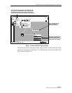
collocated or reside at remote sites. When a user selects a node, it is highlighted by
a white square that surrounds it. By double clicking on one of these nodes with the
left mouse button, a new window is displayed reflecting the interconnecting
relationship between the Primary and Secondary nodes. It is at this point that the
user can determine the number of nodes involved. Refer to Figure 1-6. The Primary
node now appears as a normal size ICON and the ring network interconnections are
not displayed. To return to the ring network view, the operator clicks on the Cancel
button at the bottom of the window.