


1152700 • Issue 1 • February 2001 • Section 2 Operations and Maintenance
Page 2-63
© 2000, ADC Telecommunications, Inc.
DLP-704
Page 1 of 2
CONNECT NMS OR X-TERMINAL ETHERNET CABLE TO THE NMIC EIM SNMP PORT
Summary: This procedure provides instructions for connecting an external Network
Management System (NMS) or X-Terminal to the NMIC EIM 10 Base-T Ethernet port on the
NMIC EIM at the rear of the shelf. The cable from customer monitoring equipment (X-Term,
etc.) must be equipped with an RJ45X LAN connector. The function of the 10 Base-T Ethernet
port is to provide the System Administrator with capabilities of monitoring system and network
alarms, provisioning virtual paths/connections, and performing maintenance and provisioning
functions. The connection will allow access to either NMIC using a shared IP address, or an
individual NMIC using a NMIC specific IP address.
Caution: Modules can be damaged by static electrical discharge. Before handling any
modules connect your wrist to an equipment ground using an approved anti-static wrist
strap. Ensure that all un-installed modules are stored in anti-static packing material.
When working with modules, always place the module on an electrically grounded
approved anti-static mat.
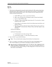
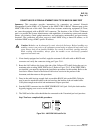
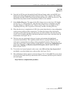
1. If not already equipped and verified, equip the customer LAN cable with an RJ45X male
connector and verify the connector wiring per Figure 704-1.
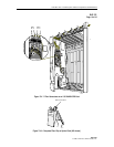
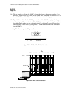
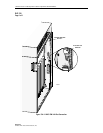
2. Route the LAN cable to the lower right side of the Cellworx STN shelf (facing the rear), to
terminate at the working NMIC EIM in slot 2. Refer to Figure 704-2. If the NMIC EIM is
not installed, you must first perform the installation procedure for this module. Refer to the
Installation Manual listed in the Related Publications section in the preface of this
document, and then return to this procedure.
3. Dress in the cable leaving enough slack to reach the RJ45X jack on the EIM. Cable ties
may be used to attach the cables to the tie bar along the bottom of the air intake baffle.
Verify that enough strain relief and maintenance loop are provided.
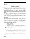
4. Seat the RJ45X connector into the NMIC EIM RJ45X LAN jack. Verify the latch catches
by gently tugging once or twice on the cable.
5. The NMS end of the cable should then be connected to the X-terminal per local practices.
Stop! You have completed this procedure.
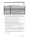
RJ45 JACK
1
8
1
2
3
4
5
6
7
8
TRANSMIT +
TRANSMIT
RECEIVE +
NOT USED
NOT USED
RECEIVE
NOT USED
NOT USED
PIN FUNCTION
10529-A
Figure 704-1. NMIC EIM RJ45 Jack Pin Out