


1152700 • Issue 1 • February 2001 • Section 2 Operations and Maintenance
Page 2-52
© 2000, ADC Telecommunications, Inc.
DLP-701
Page 7 of 10
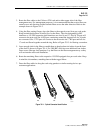
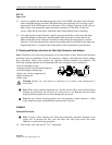
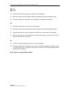
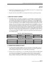
28. For D4 and FC types, align the key with the slot in the adapter.
29. Push the connector into the adapter until the coupling nut reaches the adapter housing.
30. Screw the coupling nut clockwise onto the adapter to complete the connection.
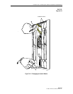
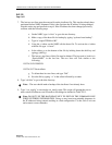
ST
®
31. Align the ferrule hub key with the slot in the adapter.
32. Insert the connector into the adapter until the coupling nut reaches the adapter housing.
33. Align the bayonet slots on the coupling nut with the pins on the outside of the adapter.
34. Push the coupling nut onto the adapter while rotating the coupler nut clockwise to lock the
bayonet and secure the connection.
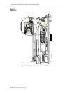
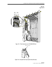
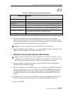
SC
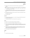
35. For the SC, align the housing key with the slot in the adapter.
36. Push the connector into the adapter until a click is heard/felt indicating the latching system
is engaged. When fully engaged, the white stripes on the sides of the SC housing should be
hidden inside the adapter.
Stop! You have completed this procedure.