


1152700 • Issue 1 • February 2001 • Section 2 Operation and Maintenance
Page 2-250
© 2000, ADC Telecommunications, Inc.
DLP-754
Page 6 of 7
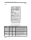
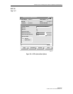
Cellworx Vision: ATM Interface
Apply
Card View
Refresh Close
X
Node Name: Cellworx1
Node Id: 1
Location: 5th Street
Slot Number: 8
Card : T1 MULTI 1
Port Number: 1
Interface Name: Slot8_Port1 DS1CESUNI
Loopback Location Code:
Recording Interface ID:
1111111111111111
0000000000000000
Provisioned Endpoints:
Number of VPCs: 0
Number of VCCs: 0
Interface Type: CAC Formula:
UNI
NNI
PCR Based
SCR Based
Policing
Cell Scrambling
Over Subscription Rate (%):
(100-10100
VP/VC Allocation:
Max Active VPI Bits:
0
012345678
Max Active VCI Bits:
1
01234567891
Max Number of VPCs:
Max Number of VCCs:
(1-1)
(0-256)
Error Log:
13431-A
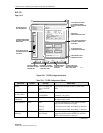
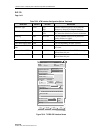
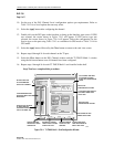
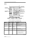
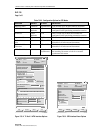
Figure 754-3. ATM Interface Menu Options
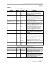
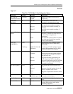
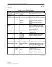
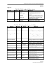
Table 754-4. Configuration Options for CES Mode
SELECTION DEFAULT OPTIONS DEFINITIONS
Interface Name <default> Alphanumeric User defined, up to 20 alpha numeric characters.
ATM VPI
<user
defined>
0-8
This is a read only to show the available bits
configured for this port during connection creation.
ATM VCI
<user
defined>
0-10
This is a read only to show the available bits
configured for this port during connection creation.
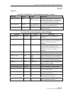
Operational State Up Up/Down This is a read only to show the state of the port.
Buffer Maximum
Size
<default> 5300 to 6220
Maximum size measured in microseconds and
selectable in 10 microsecond increments.
Cell Arrival Jitter
Tolerance
<default> 950 to 2650
Maximum size measured in microseconds and
selectable in 10 microsecond increments.
CBR Clock Mode <default>
Adaptive or
Synchronous
Sets the Constant Bit Rate clock to either adapt to
the incoming bit stream or look for a constant
synchronous bit stream.