


1152700 • Issue 1 • February 2001• Section 2 Operation and Maintenance
Page 2-415
© 2000, ADC Telecommunications, Inc.
DLP-792
Page 3 of 4
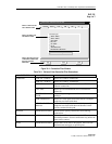
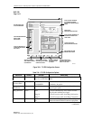
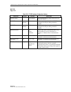
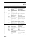
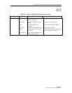
Table 792-1. T3 CES Configuration Options, continued
SELECTION DEFAULT OPTIONS DEFINITIONS
Transmit Vendor Circuit
ID
default User Defined Can be used to assign a name to the port to
identify certain customer circuits.
Line Coding B3ZS Not User
Configurable
Display only of the line coding.
Line Type Clear
Channel
Not User
Configurable
Clear Channel only. No line type interfacing is
performed. What transmission type comes in is
transported across the network unchanged.
Loopback Config. None None
Facility Line
Terminal
No loopback activated on this card.
Loops the incoming signal back to the CPE and
generates AIS to the cellbus.
Sends cells back to the cellbus and back out to
the ring. No changes are made to the path layer.
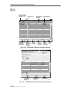
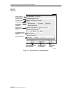
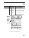
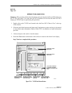
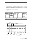
Cellworx Vision: CES Interface
Apply
Card View
Refresh Close
X
Node Name: Cellworx1
Node Id: 1
Location: 5th Street
Slot Number: 9
Card : T3 CES
Port Number: 1
Interface Name:
Slot9_Port1 DS3CESUNI
ATM VPI:
ATM VCI:
Operational State:
Buffer Maximum Size:
Cell Arrival Jitter Tolerance:
Adaptive
Synchronous
0
0
Up
microseconds1600
microseconds600
CBR Clock Mode
SRTS
APPLIES
CHANGES.
BRINGS CARD
VIEW TO FRONT.
REFRESHES
WINDOW
WITH ANY
NEW INFO.
CLOSES WINDOW
WITHOUT SAVING
CHANGES
DISPLAY ONLY OF
VPI AND VCI IDs.
DISPLAY ONLY.
USER SETABLE.
USER SETABLE.
SET CLOCK MODE
PER REQUIREMENTS.
DISPLAYS CARD,
PORT, AND NE
INFORMATION.
ASSIGN INTERFACE
NAME OR USE
SYSTEM DEFAULT.
0026-007
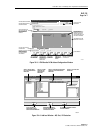
Figure 792-2. T3 CES Interface Configuration Screen