


1152700 • Issue 1 • February 2001 • Operation and Maintenance
Page 2-358
© 2000, ADC Telecommunications, Inc.
DLP-785
Page 2 of 7
Note: The user may not change the Port Mode if there is an existing interface
configured on that port.
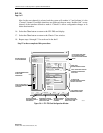
8. Click and drag the small block to expand the Port Level configuration section of the
window.
9. Select a Port on the simulated card by a single click on the port LED using the left mouse
button. This will bring up the configuration data for that port in the Port Level section of
the window. Ensure the Administrative State is set to Unlocked to enable the port for
service.
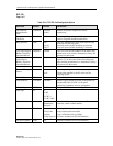
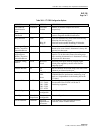
10. Set the Port Level configuration options per requirements. Refer to Table 785-2 for a list of
options the user may select for this card type.
11. Hit the Apply button at the bottom of the window to back up the new configuration data to
the shelf controller and configure the port before attempting to create interfaces on the port.
Note: Selecting Chassis View will return the user to the previous window without
closing the FT1 FRS window. Selecting Refresh will update the current window display
with all the selections last recorded by the Shelf Controller card. Selecting Close will
close this window and return the user to the Chassis View window.
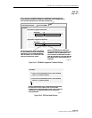
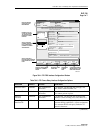
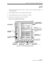
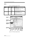
12. Double click on the port just configured (1 to 8, depending on Port Mode selected) to bring
up the Frame Relay Interface screen. Refer to the example shown in Figure 785-4. Within
this screen, the user may elect to change the port interface by double clicking on the port
desired in the Circuit box on the left.
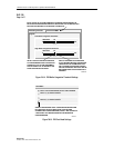
13. There are 24 DS0 channels selectable for the interface in the Interface Selection block of
the window. If creating a Channelized connection, the user may create up to 24 single
interfaces, or multiple interfaces made up of any number of contiguous channels using this
tool. If creating a Fractional connection, the user may select up to 24 channels to create a
single interface one time. The system will then indicate “Interface Creation Disabled”.
Select the individual or range of DS0 channels to create the first interface using the left
mouse button. Click on the first channel and then on the last contiguous channel of the
range. The channels will become white and are shown linked by a bracket in the window.
The GUI indicates this is the number 1 interface and shows it as the “Current” selection.
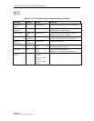
14. In the main block of the window the user can assign multiple identifiers, and configure the
interface. Refer to Table 785-3 for definitions of each option. Once all interface data is
entered, select the Apply button at the bottom of the screen to create the interface on the
port.
15. The user may now select the next channel(s) for another channelized interface and repeat
step 13 or select Close and return to step 9 to create the next Port Level configuration. If
creating another channelized interface on this port, the user will notice the color changes to
blue for the next channel(s) selected and the system will number it 2 and indicate it is the
“Current” channel. If multiple interfaces are displayed, the user must “double-click” on any