


1152700 • Issue 1 • February 2001 • Operation and Maintenance
Page 2-392
© 2000, ADC Telecommunications, Inc.
DLP-790
Page 1 of 14
CREATE AN ATM VC BUNDLED MULTICAST CONNECTION
Summary: This procedure describes the steps required to provision a UBR, CBR or VBR real
time or non-real time VC bundled multicast connection through the Cellworx STN network.
Multicasting is an extension of point to point CRS which allows the user to establish uni-
directional PVCs to transport ATM cells across the Cellworx ring from one NE (called root) to
one or more NEs (called leaves). Creating a VC multicast connection entails selecting the
originating and terminating NEs, cards, ports and interfaces. For Frame Relay connections refer
to DLP-786 and for ATM VP Multicast connections, refer to DLP-787. Traffic contracts will
also be covered in this procedure. Prerequisites of establishing a connection are:
• A discovery must have been performed on the system.
• The connection endpoints hardware (cards/ports) must be provisioned and in service
(unlocked) per NTP-006.
Note: User may navigate through the GUI menus using the mouse or by using the Alt
key plus the underlined letters in the menus simultaneously, and then the arrow keys to
scroll up, down, or across. Refer to the Graphical User Interface Operation in Section 2
of this document.
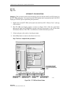
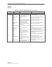
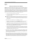
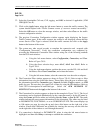
1. There are three ways to initiate the process of establishing a connection.
a. Using the left mouse button, select the Configuration pull-down menu, click on
Connection, and then Create (or press Alt+C, Alt+N, Alt+C.) Refer to Figure 790-1.
b. Using the Select tool (arrow) on the left toolbar, select the NE where the connection is
originating by a click and hold on the right mouse button. A pop-up window appears as
shown in Figure 790-1. Continue holding down the right mouse button and move the
cursor to select Create Connection. Release the mouse button.
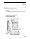
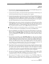
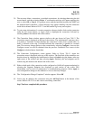
c. Using the left mouse button, select the connection tool on the toolbar to the left of the
workspace. Click and hold the left mouse button down on the NE where the connection
is originating and drag to the destination NE. A line is drawn between the two NEs as the
crosshair pointer progresses. Refer to Figure 790-2.
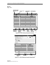
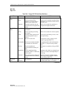
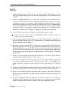
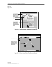
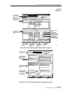
2. The Cellworx Vision Connection Configuration window appears displaying all NEs
discovered in the network in both the top section and the bottom section of the window.
Refer to Figure 790-3. Ensure the originating and destination NEs are highlighted, if not,
select them using the left mouse button.
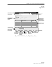
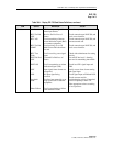
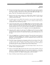
3. Enter an identification for the connection in the Connection Name text box using any
alphanumeric and special characters. This ID should be unique in character so the user can
discern between it and other connections for management purposes. The IDs assigned here
will be displayed when viewing connections. The system will allow duplicate connection
names but will also assign a unique ID to the connection if the user does not enter one.