


1152700 • Issue 1 • February 2001 • Section 2 Operation and Maintenance
Page 2-255
© 2000, ADC Telecommunications, Inc.
DLP-755
Page 4 of 5
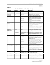
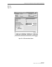
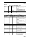
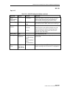
Table 755-1. T1 Multi 1 Configuration Options, continued
SELECTION DEFAULT OPTIONS DEFINITIONS
Loopback Config None None
Facility Payload
Terminal
Facility Line
No loopback activated on this card.
Loops the payload after line data is
extracted.
Sends cells to the cellbus and back to the
ring. No changes are made to the payload.
Loops the incoming signal back to CPE,
generates AIS to the cellbus.
Circuit Identifier <blank>
Up to 20 alphanumeric
characters.
User defined. Usually describes the traffic,
customer, and/or channel number.
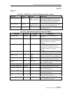
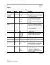
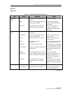
Table 755-2. ATM Interface Configuration Options for CRS Mode
SELECTION DEFAULT OPTIONS DEFINITIONS
Interface Name <default> Alphanumeric User defined, up to 20 alpha numeric
characters.
Loopback Location Code All 1s Alphanumeric Used to loopback the incoming signal and
transmit it back to the customer equipment.
The code is limited to 16 numeric
characters.
Recording Interface ID All 0s Numeric Identifies the site card and port location for
customer billing capabilities, (allows
assignment of a customer ID for each port.)
The code is limited to 15 numeric
characters.
Provisioned Endpoints Displays how many VPC or VCC endpoints
are configured by administrator on this card.
Interface Type UNI UNI
NNI
Specifies interface type as User to Network
Interface or Network to Network Interface.
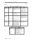
CAC Formula PCR PCR Based
SCR Based
Specifies Peak Cell Rate or Sustained Cell
Rate for Connection Admission Control.
Policing Off On or Off User sets whether traffic will be policed for
Quality Of Service (QOS).
Cell Scrambling Off On or Off User sets whether traffic will be scrambled.
Over Subscription Rate <blank> User sets depending on traffic contract.
Max Active VPI Bits 0 0 to 8 Sets the maximum number of bits that may
be utilized from this port.
Max Active VCI Bits 0 0 to 12 Sets the maximum number of bits that may
be utilized from this port.
Max number of VPCs 256 0 to 256 Sets the maximum number of VPCs that
may be utilized from this port.
Max number of VCCs 0 0-8192 Sets the maximum number of VCCs that
may be utilized from this port.