


1152700 • Issue 1 • February 2001 • Operation and Maintenance
Page 2-366
© 2000, ADC Telecommunications, Inc.
DLP-786
Page 3 of 10
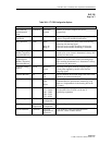
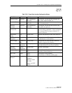
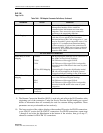
Table 786-1. FR Endpoint Parameter Definitions, Continued
PARAMETER OPTION DEFINITION
SSCS LMI Service Specific Convergence Sub-layer Link
Management Interface used to establish a
communications link between two frame relay
endpoints. These are used to report connection
problems to the transmitting endpoints.
DE Bit Tagging Discard Eligible BIT Tagging is used to identify
cells that are over and above the Committed
Information Rate (CIR). Cells are tagged as “1” and
may be discarded if system congestion occurs. Cells
tagged as “0” are buffered and transmitted during
system congestion. If selected, the connection will
be treated as NRT-VBR3 (non-real time variable bit
rate level 3). If not selected, the connection will be
treated as NRT-VBR2
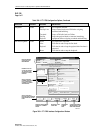
FRF.8 PVC ENDPOINT PARAMETERS
Frame Relay to ATM
Mapping
CLP=DE
CLP=0
CLP=1
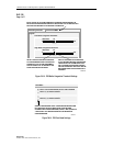
FECN to EFCI Mapping
FR Discard Eligible markings will be carried over to
the ATM Cell Loss Priority markings.
All FR frames will be tagged CLP=0.
All FR frames will be tagged CLP=1 and possibly
discarded in the ATM stream in the event of system
congestion.
Forward Explicit Congestion Notification marked
FR cells will be mapped to the Explicit Forward
Congestion Indicator markings in the ATM stream.
ATM to Frame Relay
Mapping
DE=CLP
DE=0
DE=1
ATM Cell Loss Priority markings will be carried
over to the FR Discard Eligible markings.
All FR frames will be tagged CLP=0.
All FR frames will be tagged CLP=1 and possibly
discarded in the FR stream in the event of system
congestion.
Encapsulation Transparent
Translation
?
?
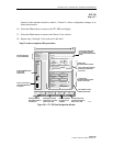
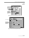
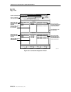
9. The Remote Connection Identifier (DLCI) is read only and reflects the DLCI number at the
originating end of the connection. Under the Service Provider Profile heading are several
blocks of information that will eventually be used for customer billing capabilities. These
parameters are not yet selectable and are read only.
10. The lower section of the window displays either another FR section for FR-FR connections,
or an ATM VC section for FR-ATM VC connections. For FR-FR connections, repeat steps
7 through 9 and select the Next button at the bottom of the window, then go to step 17,
otherwise continue for FR-ATM VC connections.