


1152700 • Issue 1 • February 2001 • Section 2 Operation and Maintenance
Page 2-240
© 2000, ADC Telecommunications, Inc.
DLP-752
Page 4of 4
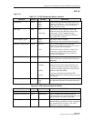
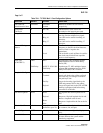
Table 752-2. ATM Interface Configuration Options, continued
SELECTION DEFAULT OPTIONS DEFINITIONS
Recording Interface
ID
All 0s Numeric Identifies the site card and port location for
customer billing capabilities, (allows
assignment of a customer ID for each port.)
The code is limited to 15 numeric characters.
UNI/ NNI Select UNI
UNI
NNI
Specifies interface type as User to Network
Interface or Network to Network Interface.
CAC Formula PCR
PCR
SCR
Specifies Peak Cell Rate or Sustained Cell Rate
for Connection Admission Control
calculations.
Traffic Policing Enable Enable
Disable
User sets whether traffic will be policed for
Quality Of Service (QOS).
Cell Scrambling True True or False User sets whether traffic will be scrambled.
Subscription Rate 100 PCR: 100 to 1000
SCR: 1 to 100
User sets depending on traffic contract.
Max Active
VPI/VCI Bits
0 0 to 12 Sets maximum number of bits allowed to select
virtual channel from.
Max number of
VPCs
4096 0-4096 Sets maximum number of virtual path circuits
that may be assigned on this port.
Max number of
VCCs
0 0-8192 Sets maximum number of virtual channel
circuits that may be assigned on this port.
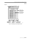
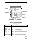
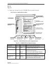
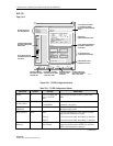
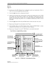
Cellworx Vision: ATM Interface
Apply
Card View
Refresh Close
X
Node Name: Cellworx1
Node Id: 1
Location: 5th Street
Slot Number: 9
Card : 155 SM CRS
Port Number: 1
Interface Name: Slot9_Port1 OC3SM
Loopback Location Code:
Recording Interface ID:
1111111111111111
0000000000000000
Provisioned Endpoints:
Number of VPCs: 0
Number of VCCs: 0
Interface Type: CAC Formula:
UNI
NNI
PCR Based
SCR Based
Policing
Cell Scrambling
Over Subscription Rate (%):
(100-10100
VP/VC Allocation:
Max Active VPI Bits:
0
012345678
Max Active VCI Bits:
0
Max Number of VPCs:
Max Number of VCCs:
(1-128)
(0-8192)
Error Log:
9101
0
4096
0
13429-B
Figure 752-2. 155 SM/MM CRS ATM Port Interface Configuration Screen