


1152700 • Issue 1 • February 2001 • Section 2 Operation and Maintenance
Page 2-245
© 2000, ADC Telecommunications, Inc.
DLP-754
Page 1 of 7
SET T3 TMUX MULTI 1 AND TMUX EXP CARD CONFIGURATION
Summary: This procedure details the steps required to set the T3 TMUX Multi 1 and TMUX
EXP (expansion) card configurations utilizing the Cellworx STN Phase 3.1 shelf level Graphical
User Interface (GUI). User must have the GUI launched, and have accessed the shelf level GUI
display per NTP-006 prior to performing this procedure.
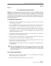
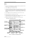
1. Double click on the T3 TMUX Multi 1 card displayed in the shelf level GUI “Chassis
View”at the top of the window. If this card has a TMUX EXP associated with it, they will
be treated as one card for configuration.
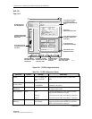
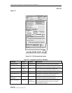
2. The T3 TMUX Multi 1 card display appears either as a single T3 TMUX Multi 1 or as
shown in Figure 754-1 as a T3 TMUX Multi 1 and TMUX EXP pair.
Note: When the T3 TMUX Multi 1 is accompanied by a TMUX EXP card, selecting
either card will result in having both cards displayed since they are treated as a pair.
3. Click and drag the small block upward to expand the Configuration section of the window
so all or most options are visible. The Administrative State of both cards and port should be
“Unlocked” if in service. If “Locked”, select the “Unlocked” option using the left mouse
button to enable either or both cards and/or port for service. To select the TMUX EXP card,
click on the tab with the correct slot number on it. This will allow the user to toggle between
the T3 TMUX MULTI 1 and TMUX EXP.
4. At the Circuit Identifier field, enter a unique ID for this circuit per work order or customer
requirements.
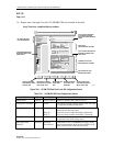
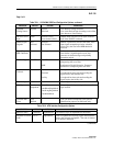
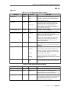
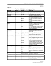
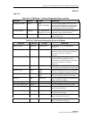
5. Set the rest of the Port Level configuration options per requirements. Refer to Table 754-1
for a list of options the user may select for this card type.
6. Hit the Apply button at the bottom of the window to back up the new configuration data to
the shelf controller.
Note: Selecting Chassis View will return the user to the previous window without
closing the T3 TMUX Multi 1 window. Selecting Refresh will update the current
window display and all the selections last recorded by the Shelf Controller card. Selecting
Close will close this window and return the user to the Chassis View window.
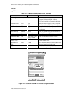
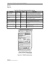
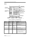
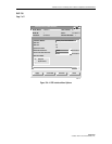
7. Click on the DS1 Channel tab shown on the simulated T3 TMUX Multi1 card view. This
will bring up the DS1 Channel view as shown in Figure 754-2.
8. Select a DS1 channel that needs to be configured at the upper left block of the screen above
the card view.
9. Again, the Administrative State of the channels should be “Unlocked” if in service. If
“Locked”, select the “Unlocked” option using the left mouse button to enable the channel
for service.