


1152700 • Issue 1 • February 2001 • Section 2 Operations and Maintenance
Page 2-47
© 2000, ADC Telecommunications, Inc.
DLP-701
Page 2 of 10
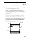
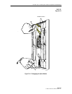
3. Route the fiber cables to the Cellworx STN rack and to either upper side of the fiber
management tray. For management purposes, it is recommended that the receive fibers are
routed across one direction and the transmit fibers across the other direction. Refer to the
example shown in Figure 701-2.
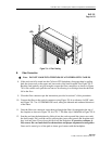
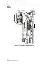
4. Using the fiber routing flanges, dress the fibers to the respective card slots per work order.
Keep in mind the direction of traffic flow for the fibers. The slots designated for RIC
interfaces or 155 CRS expansion shelf interfaces are slots 16 and 17. Slot 16 TX port will
connect to the next node slot 16 RX port, continuing around the ring until all slot 16 cards
are connected. Slot 17 TX port will connect to the next node slot 17 RX port until all slot
17 cards are fibered together around the ring. Refer to Figure 701-3 for fibering convention.
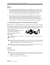
5. Leave enough slack in the fibers to enable them to dangle about six inches down the front
of the shelf as shown in Figure 701-4. For 2488 RIC cards leave an additional four inches.
Dress excess fiber per local practices. Lay the fibers on the fiber management tray so they
will not interfere with card installation.
6. Route the remaining fibers to the respective 155 CRS equipped slots per work order. Keep
in mind the slot numbers, matching them with the tagged fibers.
7. Dress the fiber cables in along the rack using panduct or similar routing devices per
customer applications.
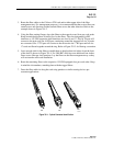
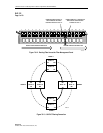
FC
ST
SC
10518-A
Figure 701-1. Optical Connector Identification