


ADCP-70-220 • Issue 1 • November 2000 • Section 2 Operation and Maintenance
Page 2-16
© 2000, ADC Telecommunications, Inc.
NTP-006
Page 3 of 5
B. CARD CONFIGURATIONS
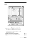
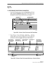
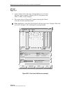
7. Card configuration screens may be accessed from the shelf level
GUI Chassis View window by double clicking on the card
desired. Select a card and refer to the following card level GUI
procedures to set the configuration options for that specific card
type:
• Set the E1 Multi 1 card configuration options. DLP-747
• Set the 622 RIC card configuration options. DLP-751
• Set the 155 SM/MM CRS (OC3) card configuration options. DLP-752
• Set the 622 SM CRS (OC12) card configuration options. DLP-797
• Set the T3 CRS card configuration options. DLP-753
• Set the T3 TMUX MULTI 1 configuration options. DLP-754
• Set the T1/E1 MULTI 1 card configuration options. DLP-755
• Set the 2488 RIC card configuration options. DLP-756
• Set the 155 RIC configuration options. DLP-758
• Set the FE1 FRS card configuration options. DLP-784
• Set the FT1 FRS card configuration options. DLP-785
• Set the T3 CES card configuration options. DLP-792
8. Configure card protection groups, if applicable, for each access
interface card type. DLP-765
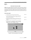
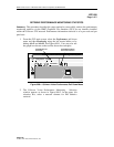
9. Verify that the required cards show that they are equipped and
in-service by observing the shelf level GUI screen. Any cards
not provisioned for service will show up as “grayed out”. If any
required cards are grayed out, return to the correct procedure
outlined in Step 7 of this NTP, otherwise “Close” the chassis
view and continue with step 10.
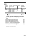
Note: In a 19-inch shelf, slot 12 through 15 will always show up as “grayed out” and the
last three slots will always be treated as slots 16, 17, and 18 even though there are
physically only 14 slots available.
10. Set the alarm level threshold for the shelf. DLP-717
11. Repeat this procedure for each shelf in the ring.