


1152700 • Issue 1 • February 2001 • Section 2 Operation and Maintenance
Page 2-184
2000, ADC Telecommunications, Inc.
DLP-737
Page 1 of 8
ADD A RING NETWORK ELEMENT
Summary: This procedure describes the steps required to add a new Cellworx STN ring node to
an existing in service ring network. During this procedure the technician will be required to
disconnect fibers in the existing system and reconnect them to the new node. The Graphical User
Interface (GUI) will step the technician through this process without causing traffic loss in the
network. The instructions provided by the GUI should be followed precisely to minimize service
impact on the upgrade. If adding a second node to a stand-alone terminal, refer to NTP-004 for
the proper procedure.
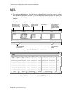
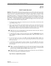
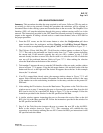
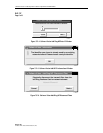
1. From the GUI screen, use the left mouse button to select the Configuration pull down
menu located above the workspace, and then Topology and Add Ring Network Element.
This can also be accomplished by entering Alt+C, Alt+T, and Alt+A. Refer to Figure 737-1.
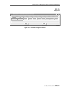
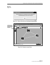
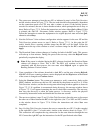
2. The Cellworx Vision: Add Ring NE - Task Overview window appears as shown in Figure
737-2. The tasks to be performed are listed in order from 1 to 17 with a pointer indicating
the current task. If the network currently has only two NEs, continue to step 3. If the
network already has three or more NEs, the first task is to select the two NEs in which the
new one will be positioned between. Refer to Figure 737-3. After making the selection
select the Next button at the bottom of the window.
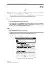
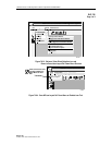
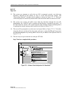
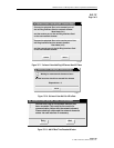
3. Task number 2 instructs the user to enter the NE identifier of the new node, and the window
shown in Figure 737-4 appears. Using the left mouse button, click and hold on the slide bar
button and move it to the right until the desired ID appears above the bar. In this example
shown, the 2 is selected.
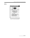
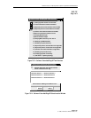
4. If an ID is entered that already exists, the message window shown in Figure 737-5 will
appear. Select OK and choose another ID number. Be sure the number selected is the same
as the number set on the node during installation via the rotary switches on the protect SC
EIM card.
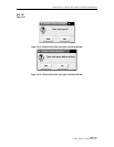
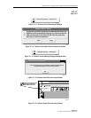
5. After making the ID selection, choose the Next button. The pointer on the Task Overview
window moves to step 3, instructing the user to disconnect the transmit fiber from the left
RIC (card in slot 16) on a specified NE. Refer to Figure 737-6 for an example. Follow the
instructions provided in the window for the NE specified and hit Next.
6. A similar window appears instructing the user to disconnect the receive fiber on the left
RIC (slot 16) in the other specified NE. Follow the instructions provided in the window for
the NE specified and hit Next.
7. Step 5 of the Task Overview instructs the user to connect the new NE to the left RICs.
Refer to the window shown in Figure 737-7. This connection will establish the ring
connection in one direction utilizing the new NE. Connect left RICs per instructions for the
NE specified and select Next.