


1152700 • Issue 1 • February 2001 • Operation and Maintenance
Page 2-375
© 2000, ADC Telecommunications, Inc.
DLP-787
Page 2 of 12
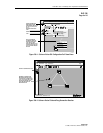
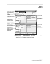
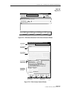
4. Next specify the connection type by left mouse clicking on the Connection Type pull down
menu and selecting ATM VP MULTICAST.
5. Using the left mouse button, select the desired Root Network Element, Slot/Card Type, and
Network Interface/Interface Type for the originating “Root” endpoint.
6. Using the left mouse button, select the desired Leaf Network Element, Slot/Card Type, and
Network Interface/Interface Type for the destination “Leaf” endpoint. After highlighting
the Interface Type, select the Add button to define the Interface Type as a Leaf Interface.
The Interface Type should now be displayed in the Leaf Interface box to the right of the
screen and is removed from the available Leaf Interfaces box.
7. Multiple interface types may be selected as leaf interfaces by selecting them, clicking on
the Add button, and moving them to the Leaf Interface box. Only one port per card is
supported for release 3.1 software packages. Once all leaf interfaces are selected for the VP
multicast connection, click on Next>> using the left mouse button.
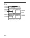
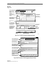
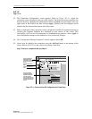
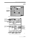
8. The next configuration screen displays the root and leaf network elements in a split screen.
Refer to Figure 787-4 for an example. At the Root Network Element upper section of the
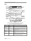
screen, select the Segment Endpoint and Ingress NDC if desired. Refer to Table 787-1 for
definitions of each option selectable by the user.
9. Using the left mouse button select VPI from the list provided in the VPI/NE/Rate box to be
utilized at the Root NE. The VPI will become highlighted. These were defined during the
card interface configuration. Refer to NTP-009 for configuration procedures on each card
type if needed.
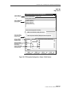
10. Configure the Service Provider Profile if desired again referring to Table 787-1 for
definitions.
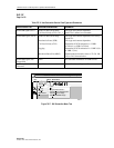
11. At the Leaf Network Element lower section of the screen, select the Segment Endpoint and
Egress NDC if desired. Refer to Table 787-1 for definitions of each option.
12. The interfaces selected from the previous screen are displayed in the “Leaf Interface” box.
If they are already “configured”, they will have two asterisks preceding the identification,
otherwise they may still be selected for configuration. Using the left mouse button, click on
the interface to highlight it.
13. Next select a VPI interface displayed in the VPI/NE/Rate (Kbps) box. These were defined
during the card interface configuration. Refer to NTP-009 for configuration procedures on
each card type if needed. Once the VPI are selected, the Update Leaf button below becomes
selectable.
14. Configure the Service Provider Profile if desired again referring to Table 787-1 for
definitions.