


1152700 • Issue 1 • February 2001 • Section 2 Operation and Maintenance
Page 2-203
2000, ADC Telecommunications, Inc.
DLP-740
Page 1 of 5
DELETE A CELLWORX STN NODE
Summary: This procedure describes the steps necessary to successfully delete a Cellworx STN
node from the system database. Pre-requisites of this procedure are:
• The user should have gained access to the Cellworx STN system and have
launched the GUI.
• All connections to the NE that is being removed from the system database
should have all connections deleted.
1. Select the node to be deleted using the left mouse button. A white ring surrounds the node.
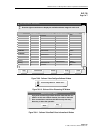
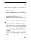
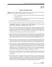
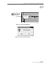
2. Access the Remove Ring NE Task Overview window using the left mouse button to select
Configuration, Topology, and Remove Ring Network Element (or using the direct
selection keys, Alt+C, Alt+T, then Alt+M). Refer to Figure 740-1.
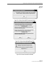
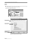
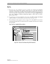
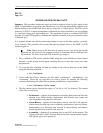
3. The task overview window appears as the system checks for existing connections. Refer to
Figure 740-2. Step 2 of the task overview brings up a window instructing the user to
disconnect the transmit fiber from the left RIC of the next NE in the network (ID will be
displayed). Refer to Figure 740-3. The left RICs are installed in slot 16. Follow the
instructions for disconnecting the fiber and select the Next >> button.
4. Step 3 of the task overview instructs the user to disconnect the receive fiber from the left
RIC (slot 16) of the previous NE in the network. This isolates the NE being removed from
the inner fiber route of the network and leaves the traffic flowing through the NE in the
outer direction. Follow the instructions to remove the fiber and select the Next >> button.
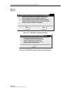
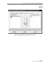
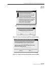
5. Step 4 of the task overview instructs the user to reconnect the transmit fiber of the next NE
to the receive fiber of the previous NE in the network thus restoring the ring inner fiber
connections. Refer to Figure 740-4. Follow the instructions and select the Next >> button.
6. The system forces all traffic on the ring to the inner fiber direction so the previous steps
may be repeated on the outer ring fibers between the NE being removed and the previous
and next NEs in the network. The system prompts the user to remove the fibers from the
right RICs in slot 17 of the NEs with windows similar to Figures 740-3, and reconnect them
to each other similar to the window in Figure 740-4 (tasks 5 to 7). Follow the instructions
for each window and select the Next >> button on each window to continue.
7. The system restores the ring traffic over both fibers and begins discovering the physical
ring connectivity (step 8). Once the software verifies all physical fiber connections, the task
is completed.
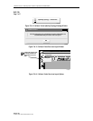
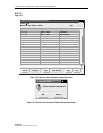
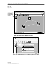
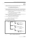
8. When the NE removal is completed, the system draws the new ring configuration on the
screen according to its connectivity. To redraw the icon layout before saving the default
system layout, select the arrow tool on the toolbar on the left side of the screen, click on
and drag the NEs to the desired position on the screen, and release the mouse button. See
Figure 740-5. This does not change the physical connectivity between the nodes.