


1152700 • Issue 1 • February 2001 • Section 2 Operations and Maintenance
Page 2-49
© 2000, ADC Telecommunications, Inc.
DLP-701
Page 4 of 10
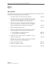
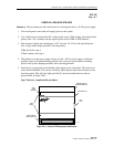
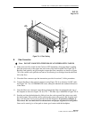
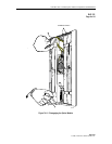
FIBER
ROUTING
FLANGES
10721-B
Figure 701-4. Fiber Routing
B. Fiber Connection
Note: DO NOT LOOK INTO THE ENDS OF ANY FIBER OPTIC CABLES.
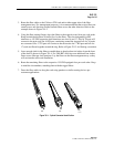
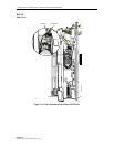
8. If the cards are fully seated into the Cellworx STN backplane, disengage them by pulling
back the ejector ears on the upper and lower ends of the card faceplate. See Figure 701-5.
Back the card partially out just enough to expose the fiber connections as shown in Figure
701-6. Be careful not to pull the card out too far allowing it to dislodge from the shelf and
fall to the floor.
9. Clean the fiber connectors per the instructions provided in section C of this proceedure.
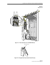
10. Connect the fibers to the optical connectors using Figure 701-6 as reference for RIC cards,
and Figure 701-7 for 155 SM/MM CRS cards, noting the inbound and outbound directions
of the fibers.
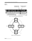
11. Once the fibers are connected, route them up through the fiber clip equipped at the top of
the faceplate as shown in Figure 701-6 or 701-7. The fiber clip is identified in Figure 701-8.
12. Seat the card into the backplane by sliding it into the card cage until the ejector ears catch
the shelf trough. Fully seat the card by pressing the ejector ears towards the faceplate until
they lock into place. Do not force the cards into the backplane. If excessive resistance is
felt, remove the card and check for obstructions and proper alignment in card guides.
Once card is seated, give a firm push to insure good contact with the backplane.