


ADCP-70-220 • Issue 1 • November 2000 • Section 2 Operation and Maintenance
Page 2-20
© 2000, ADC Telecommunications, Inc.
NTP-007
Page 2 of 3
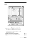
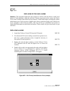
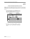
5. Again, double click on the node with the highest level of alarm
(red, then yellow) whether a Primary (NE-2) or Expansion node
(EPS-1 or EPS-2 in this example).
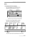
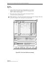
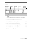
6. The screen shown in Figure 007-2 appears showing the Chassis
View and all cards associated with it.
Note: Applications using the 19-inch chassis will show card slots 1 through 18 but only
card slots 1 through 11 and 16 through 18 are programmable.
Cellworx Vision: Chassis View, Network Element 2
File Configuration Fault Security
123456789101112131415161718
S
C
N
M
I
C
S
C
6
2
2
R
i
n
g
6
2
2
R
i
n
g
Status:
Power Status: normal
Identifier:
Start Time:
Vendor:
2
19:30:47 8/31/1999
ADC-TSG
Alarm Status:
Version:
Current Time:
Up Time:
minor
1.2.0.35
10:12:09 09/01/1999
1d 19:41:22:00
Configuration:
Name:
Location:
Memory Utilization Threshold:
Suppress Zero Stats
Cellworx2
5th Street
Apply Topology View
Refresh Close
X
T
3
T
M
U
X
T
M
U
X
E
X
P
T
1
M
u
l
t
i
1
T
3
C
R
S
T
3
C
R
S
E
1
M
u
l
t
i
1
13455-B
E
1
M
u
l
t
i
1
1
5
5
S
M
C
R
S
Figure 007-2. Shelf Level GUI Screen (example)