


Configuring Frame Relay FRF.8 Circuits
212 Avidia System Configuration and Management User Manual
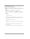
Adding a Frame Relay FRF.8 Circuit
From the ::frf8=> prompt, type the new command in the following format then press
. The index number and the frame relay VPI/VCI on the frame card are automatically
assigned.
new <fslot.port> <dlci> <lslot.port> <lvpi> <lvci>
[-admin (up|down)] [-lpmode (1|2)] [-lpvalue (0|1)]
[-cimode (1|2)] [-demode (1|2)] [-devalue (0|1)] [-CIR <value>]
[-Be <value>] [-Bc <value>] [-type (ubr|cbr|nrt-vbr|rt-vbr)]
Parameters
<fslot.port>
The frame card slot and port.
<dlci>
The DLCI (Data Link Connection Identifier) is the logical channel a data frame travels
from the transmitted device to the destination device. The valid range is 16 to 991.
<lslot.port>
The line card slot and port (format slot.port).
<lvpi>
The ATM VPI of the frame relay (fr) VCC between the frame channel card and the line
card.
<lvci>
The ATM VCI of the fr VCC between the frame channel card and the line card.
[-admin (up|down)]
The administrative status of the line. up activates the port, down deactivates the port.
ENTER