Chapter 3: Applications and Configuration Overview
Avidia System Configuration and Management User Manual 49
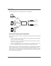
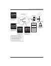
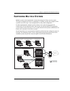
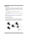
The following sections describe how to select cards for the various subtending connections. The
figures use the sample system shown above as an example.
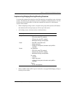
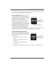
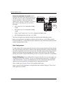
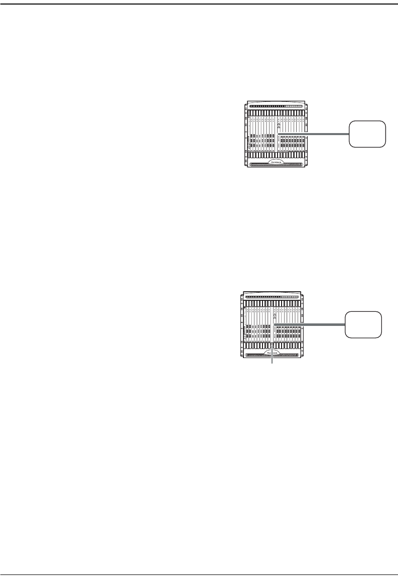
Select the uplink card. Install one card for the
network uplink, such as the ATM switch shown to
the right, in the subtending system. The card must
reside in slot 11 or 12 for an AV8000 or slot 2 for an
AV3000. Select either a DS3, an OC3, or a
DS1/DSX-1 for an AV3000 or AV8000 system.
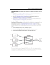
Select a card that accommodates the required
network uplink bandwidth for all the systems that are
aggregated by the subtending system. Ensure that the
subtending system’s network uplink card is not a
bottleneck for traffic. For example, use an OC3 or
DS3 card for larger systems since these cards
provide greater bandwidth. Use a DS1/DSX-1 card for an initial implementation where Avidia
systems have only a few cards with the intention of expanding service in the future.
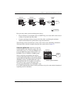
Select the subtending channel cards.
Install a card in the channel-side of the subtending
system for each system that will be subtended, up
to the maximum allowed number of cards (see the
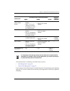
table on page 47):
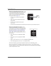
• DS1 that can be installed in any channel
card slot
• DSX-1 that can be installed in the second
line card slot
• DS3 that can be installed in the second
line card slot
• OC3 that can be installed in the second line card slot and in any two channel card slots
Network Uplink Connection
Subtending System
ATM
Switch
Card for subtending
Subtending System
ATM
Switch


