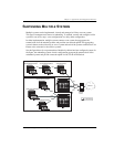
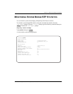
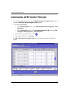
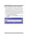
Configuring Frame Relay FRF.5 Circuits
220 Avidia System Configuration and Management User Manual
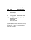
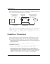
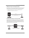
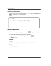
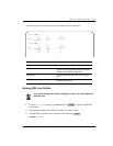
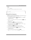
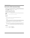
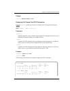
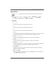
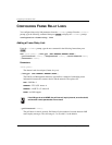
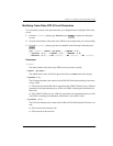
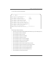
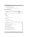
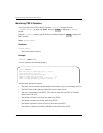
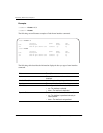
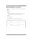
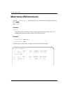
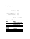
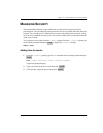
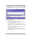
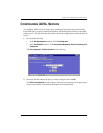
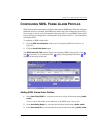
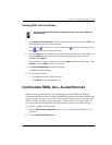
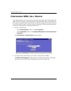
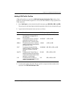
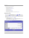
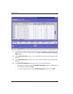
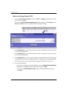
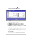
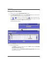
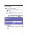
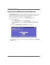
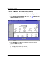
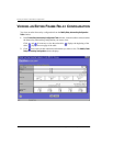
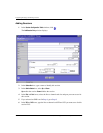
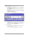
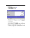
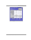
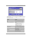
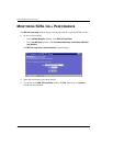
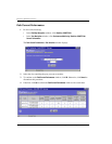
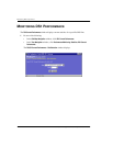
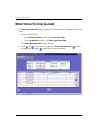
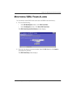
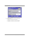
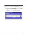
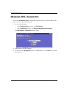
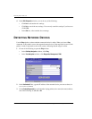
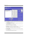
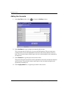
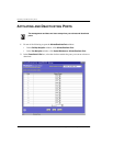
Adding a Frame Relay FRF.5 Circuit
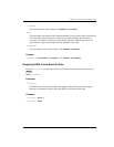
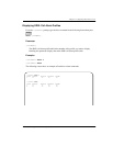
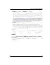
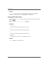
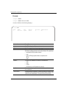
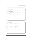
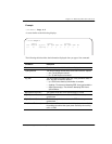
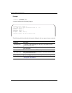
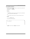
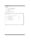
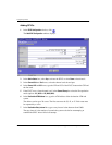
From the ::frf5=> prompt, type the new command in the following format then press
. The index number and the VPI/VCI on the frame card are automatically assigned.
new <fslot.port> <dlci> <lslot.port> <lvpi> <lvci>
[-admin (up|down)] [-txlpmode (1|2)] [-clpmask (0|1)] [-rxlpmode
(1|2)] [-CIR <value>] [-Be <value>] [-Bc <value>] [-type
(ubr|cbr|nrt-vbr|rt-vbr)]
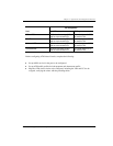
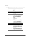
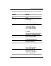
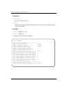
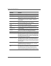
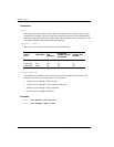
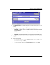
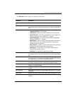
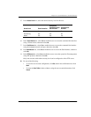
Parameters
<fslot.port>
The frame card slot and port.
<dlci>
The DLCI (Data Link Connection Identifier) is the logical channel a data frame travels
from the transmitted device to the destination device. The valid range is 16 to 991.
<lslot.port>
The line card slot and port (format slot.port).
<lvpi>
The frame relay (fr) VPI of the fr VCC between the frame channel card and the line card.
<lvci>
The fr VCI of the fr VCC between the frame channel card and the line card. When using
the range command, the first fr PVC is assigned the fr VCI you specify for this parameter.
Each additional fr PVC is assigned the next sequential fr VCI.
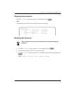
[-admin (up|down)]
The administrative status of the line. up activates the port, down deactivates the port.
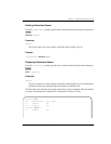
[-txlpmode (1|2)]
The Tx LP mode determines the content of the FR-SSCS (Frame Relay - Service Specific
Convergence Sublayer) PDU header DE and ATM cell ATM CLP fields.
1—The frame header DE field is copied in the FR-SSCS PDU header DE field and mapped
into the ATM CLP field of every ATM cell generated by the frame.
2—The frame header DE field is copied into the FR-SSCS PDU header DE field. The ATM
CLP field of every ATM cell generated by the segmentation process of the AAL5 PDU
containing the information of that frame is set to the CLP mask value.
ENTER