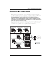
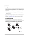
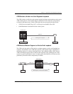
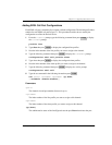
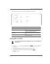
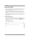
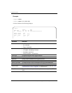
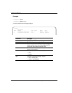
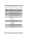
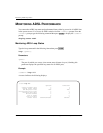
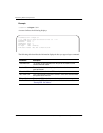
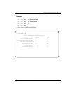
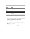
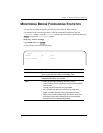
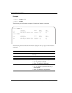
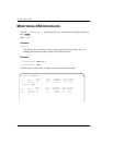
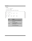
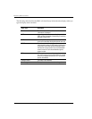
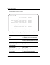
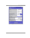
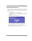
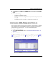
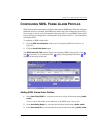
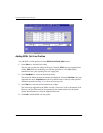
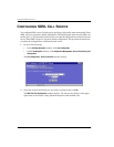
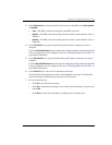
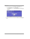
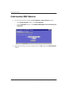
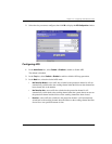
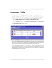
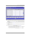
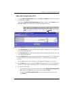
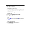
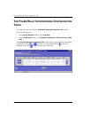
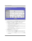
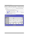
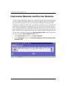
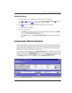
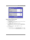
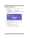
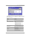
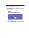
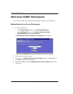
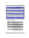
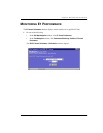
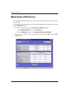
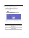
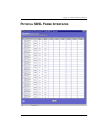
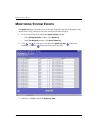
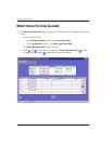
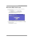
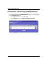
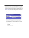
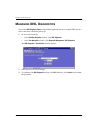
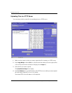
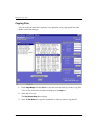
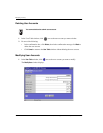
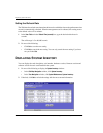
Adding a Frame Relay Configuration
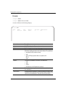
474 Avidia System Configuration and Management User Manual
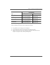
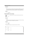
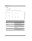
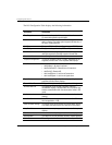
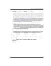
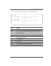
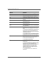
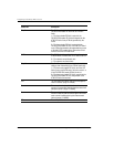
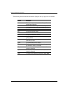
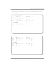
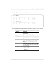
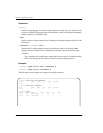
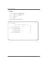
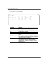
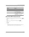
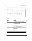
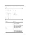
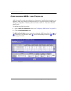
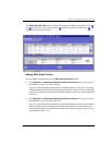
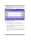
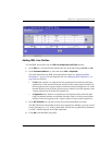
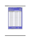
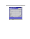
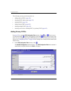
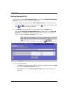
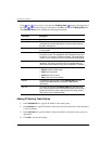
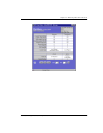
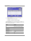
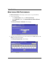
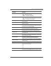
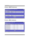
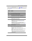
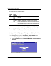
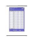
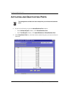
c In the CLP Mask box, select the mask used when Tx LP Mode is set to 2 (0 or 1).
The CLP Mask determines the content of the ATM cell CLP field when
Tx LP Mode is
set to
2.
0—The network cannot discard cells.
1—The network can discard cells.
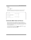
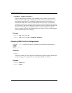
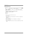
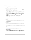
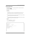
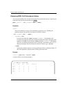
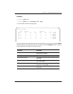
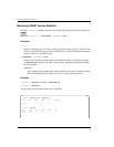
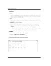
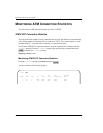
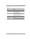
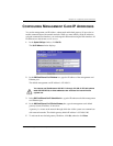
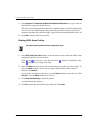
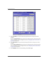
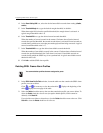
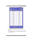
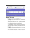
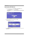
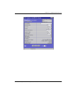
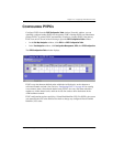
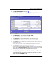
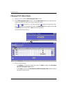
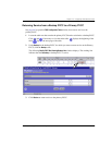
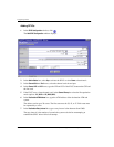
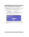
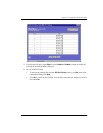
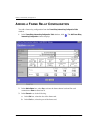
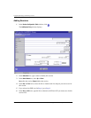
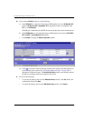
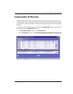
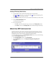
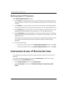
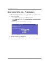
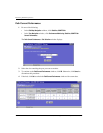
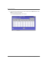
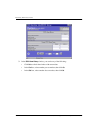
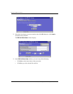
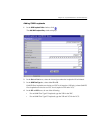
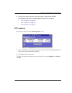
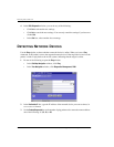
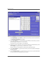
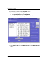
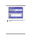
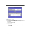
9 If you selected Interworking
FRF.8, do the following:
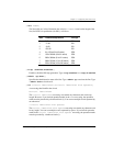
a In the
LP Mode box, select the LP Mode (1 or 2).
The LP Mode determines the content of the ATM CLP field when translating from
frame relay to ATM.
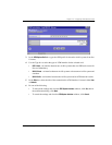
1—The frame relay header DE field is mapped into the ATM CLP field of every ATM
cell generated by the segmentation process of the AAL5 PDU containing the
information for that frame.
2—The ATM CLP field of every ATM cell generated by the segmentation process of
the AAL5 PDU containing the information of that frame is set to the
LP Value.
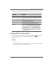
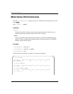
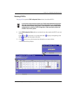
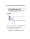
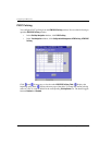
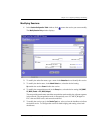
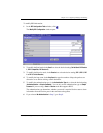
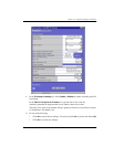
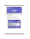
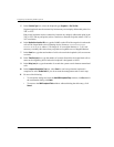
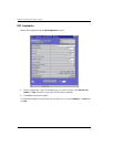
b In the
LP Value box, select the value used when LP Mode is set to 2 (0 or 1).
The LP Value determines the content of the ATM cell CLP field when
LP Mode is set
to
2.
0—The network cannot discard cells.
1—The network can discard cells.
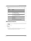
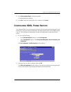
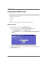
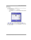
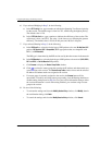
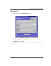
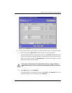
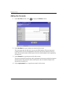
c In the
CI Mode box, select the CI Mode (1 or 2).
The CI Mode determines the content of the ATM EFCI field.
1—The frame relay FECN field is mapped to the ATM EFCI field of every ATM cell
generated by the segmentation process of the AAL5 PDU containing the information
of that frame. This mode provides congestion indication to the end points, where
higher-level protocol entries might be involved in traffic control mechanisms.
2—The ATM EFCI field is set to "congestion not experienced."
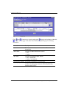
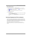
d In the
DE Mode box, select the DE Mode (1 or 2).
The DE Mode determines the content of the frame relay DE field when transmitting
from ATM to frame relay.
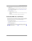
1—If the ATM CLP field of one or more cells belonging to a frame is set, the frame
relay DE field is set.
2—If the ATM CLP field of one or more cells belonging to a frame is set, the frame
relay DE field is set to the
DE Value.