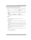
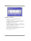
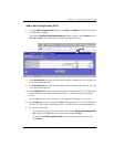
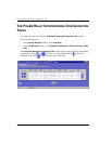
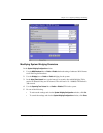
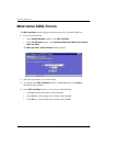
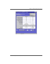
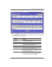
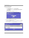
Configuring Frame Relay FRF.8 Circuits
216 Avidia System Configuration and Management User Manual
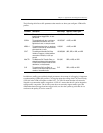
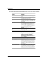
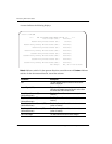
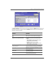
[-cimode (1|2)]
The CI Mode determines the content of the ATM EFCI field.
1—The frame relay FECN field is mapped to the ATM EFCI field of every ATM cell
generated by the segmentation process of the AAL5 PDU containing the information of that
frame. This mode provides congestion indication to the end points, where higher-level
protocol entries might be involved in traffic control mechanisms.
2—The ATM EFCI field is set to "congestion not experienced."
[-demode (1|2)]
The DE Mode determines the content of the frame relay DE field when transmitting from
ATM to frame relay.
1—If the ATM CLP field of one or more cells belonging to a frame is set, the frame relay
DE field is set.
2—If the ATM CLP field of one or more cells belonging to a frame is set, the frame relay
DE field is set to the DE value.
[-devalue (0|1)]
The DE Value determines the content of the frame relay DE field when the DE mode is set
to 2.
0—The network cannot discard frames.
1—The network can discard frames.
[-CIR <value>]
The committed information rate (circuit throughput) value in seconds. The valid range is 0
to 144000, with 0 as the default.
[-Be <value>]
The excess burst value is the maximum number of uncommitted data bits that the network
will attempt to deliver. The valid range is 0 to 144000, with 144000 as the default.
[-Bc <value>]
Committed burst is the maximum number of data bits that the network agrees to transfer
under normal conditions during the measurement interval. The valid range is 0 to 144000,
with 0 as the default.
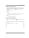
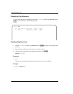
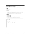
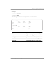
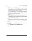
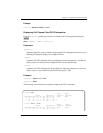
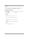
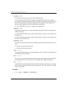
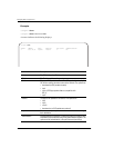
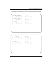
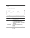
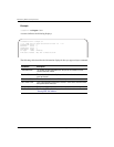
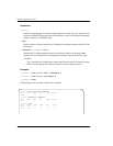
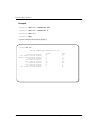
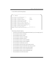
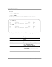
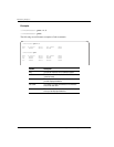
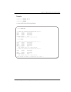
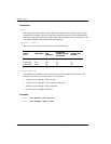
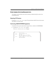
Example
::frf8=> set 1 -demode 2 -devalue 1