


Chapter 28: Monitoring System Alarms and Status
Avidia System Configuration and Management User Manual 547
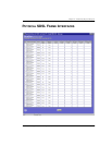
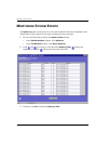
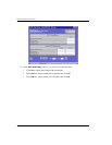
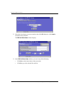
The Chassis Alarm Status Table window provides the following information:
Information Description
LED Status Displays a graphical representation of the current chassis LED status.
Green indicates there is no alarm. Red indicates an alarm. When red, the
LEDs correspond to the following:
• Critical
—A critical alarm has occurred somewhere in the system.
• Major—A major alarm has occurred somewhere in the system.
• Minor
—A minor alarm has occurred somewhere in the system.
• Audio Alarm
—An audio alarm has occurred somewhere in the system.
• Fan Alarm 1—Chassis fan 1 has failed.
• Fan Alarm 2
—Chassis fan 2 has failed.
• Fan Alarm 3—Chassis fan 3 has failed.
• Fan Alarm 4—Chassis fan 4 has failed.
• Power
—One of the chassis power inputs is down.
• Power 1—Chassis power input 1 is down.
• Power 2—Chassis power input 2 is down.
• Fuse 1
—Chassis fuse 1 is blown (not yet implemented).
• Fuse 2—Chassis fuse 2 is blown (not yet implemented).
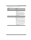
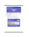
Slot The slot in which the alarm occurred.
Card Description The description of the card on which the alarm occurred.
Alarm Source The location from which the alarm was generated.