Chapter 3: Applications and Configuration Overview
Avidia System Configuration and Management User Manual 51
Configure Service. For each card that is subtending or subtended, configure the applicable
service:
• DS1/DSX-1: see “Configuring DS1 Service” on page 143 (command-line interface) or
“Configuring DS1 Service” on page 417 (Web interface)
• DS3: see “Configuring DS3 Service” on page 149 (command-line interface) or
“Configuring DS3 Service” on page 422 (Web interface)
• OC3 service: see “Configuring OC3 Service” on page 142 (command-line interface) or
“Configuring OC3 Service” on page 416 (Web interface)
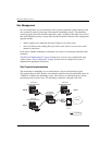
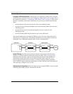
Configure ATM Connections. Configure the PVCs (ATM circuits), using the profiles that
you created for service (see “Configuring ATM Virtual Circuits” on page 153 for the
command-line interface or “Configuring ATM Virtual Circuits” on page 427 for the Web
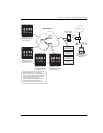
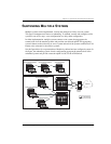
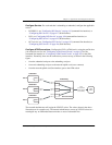
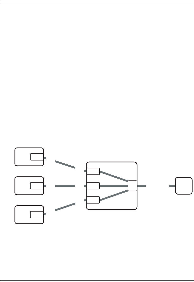
interface). Essentially, these are the connections you must set up, as shown in the following
figure:
• from the subtended card port to the subtending card port
• from each subtending card port to the network uplink card (cross-connects)
• from the network uplink card (line interface) port to the ATM switch
The network administrator will assign the VPI/VCI values. The values shown in the above
illustration are for example only. The network administrator can set up VPI/VCI values in a
meaningful way to differentiate between nodes or areas of subtended sites.
Site A
Site B
Site C
ATM
Switch
VPI 6
VCI 1
PVP
(or use three
PVCs instead
of one PVP)
VPI 6
VCI 1
DS1
DS1
DS1
VPI 3
VCI 1
VPI 9
VCI 1
VPI 9
VCI 1
VPI 3
VCI 1
Subtending
Cross-connects
DS1
OC3
DS1
DS1
Subtended
Subtended
Subtended


