


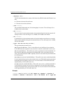

Configuring Frame Relay FRF.8 Circuits
218 Avidia System Configuration and Management User Manual
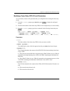
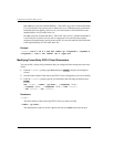
Status Box Description
Idx The index number of the frame relay FRF.8 circuit.
Fport The frame card slot and port number in the format
slot.port. For example, slot 4 port 1 would be 4.1.
DLCI The Data Link Connection Identifier (range: 16-991).
Lp The line card slot and port number in the format
slot.port.
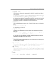
Vpi The fr VPI of the fr VCC between the frame channel
card and the line card.
Vci The fr VCI of the fr VCC between the frame channel
card and the line card.
Admn The administrative status of the line: up (activated) or
down (deactivated).
LpM The LP mode, which determines the content of the
ATM CLP field when translating from frame relay to
ATM.
1—The frame relay header DE field is mapped into the
ATM CLP field of every ATM cell generated by the
segmentation process of the AAL5 PDU containing the
information for that frame.
2—The ATM CLP field of every ATM cell generated by
the segmentation process of the AAL5 PDU containing
the information of that frame is set to the LP value.
LpV The LP value, which determines the content of the
ATM cell CLP field when the LP mode is set to 2.
0—The network cannot discard cells.
1—The network can discard cells.
CiM The CI mode, which determines the content of the
ATM EFCI field.
1—The frame relay FECN field is mapped to the ATM
EFCI field of every ATM cell generated by the
segmentation process of the AAL5 PDU containing the
information of that frame. This mode provides
congestion indication to the end points, where
higher-level protocol entries might be involved in
traffic control mechanisms.
2—The ATM EFCI field is set to "congestion not
experienced."