


Frame Relay Transmission
26 Avidia System Configuration and Management User Manual
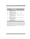
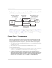
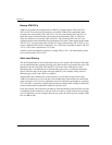
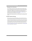
The following illustration shows an example of a configured PVC, including the specific VPI
and VCI values associated with each segment of the connection.
ATM PVCs can also be set up to run bridging, routing or brouting sessions. See “Configuring
Bridging and Routing Sessions” on page 228 (command-line interface) or “Configuring
Bridging and Routing Sessions” on page 486 (Web interface) for information about setting up
and running bridging, routing, and brouting sessions over ATM PVCs.
FRAME RELAY TRANSMISSION
Frame relay interworking allows frames to be transported by an ATM network to an ATM
device or another frame relay device. Use frame relay with the IDSL frame-based card that
attaches to modems using frame relay protocol. There are two standards for interworking:
• FRF.5 defines how frames are encapsulated so that they can be carried by the ATM network
to another frame device.
• FRF.8 defines how frames are translated between ATM and frame devices.
To set up frame relay services:
• Configure service for each IDSL frame card port (includes selecting the IDSL card transmit
clock source, and the IDSL line profile and IDSL alarm profile for each port).
• Configure the frame relay link for each port, which involves setting the LMI (Local
Management Interface) parameters. The LMI type defines the method of exchanging status
information between the customer device and the network. The available LMI types are
LMI Rev-1, ITU 0.933 Annex-A, ANSI T1 617 Annex-D, and no LMI support.
Cross-connect
PVC
VPI-0
VCI-100
VPI-250
VCI-300
VPI-250
VCI-300
VPI-0
VCI-100
OC3
card
AT M
Network
Access
Provider
Cell-Based ADSL
Channel Card
Network-side VPI/VCI values
are obtained from ATM
network access provider
Subscriber VPI/VCI values
are obtained from
ADSL access provider
Ports are mapped
to same VPI/VCI
VPI/VCI is mapped
to continue to next
network segment
Ports are mapped
to same VPI/VCI
Megabit Modem
700F
600F
500L