


7-2
ATM Switch Router Software Configuration Guide
OL-7396-01
Chapter 7 Configuring Virtual Connections
Characteristics and Types of Virtual Connections
• Input Translation Table Management, page 7-95
Characteristics and Types of Virtual Connections
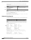
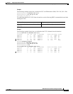
This section lists the various virtual connections (VC) types in Table 7-1.
Configuring Virtual Channel Connections
This section describes configuring virtual channel connections (VCCs) on the ATM switch router.
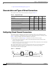
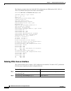
AVCC is established as a bidirectional facility to transfer ATM traffic between two ATM layer users.
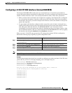
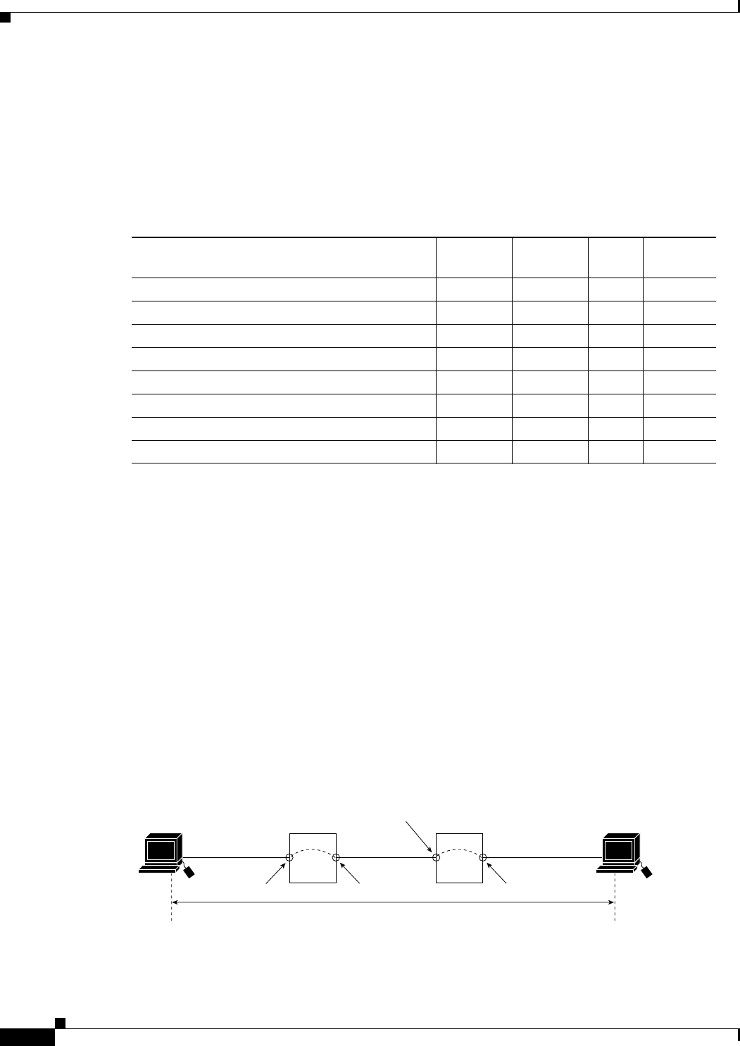
Figure 7-1 shows an example VCC between ATM user A and user D.
An end-to-end VCC, as shown in Figure 7-1 between user A and user D, has two parts:
• Virtual channel links, labelled VCL. These are the interconnections between switches, either
directly or through VP tunnels.
• Internal connections, shown by the dotted line in the switch. These connections are also sometimes
called cross-connections or cross-connects.
The common endpoint between an internal connection and a link occurs at the switch interface.
The endpoint of the internal connection is also referred to as a connection leg or half-leg.
A cross-connect connects two legs together.
Figure 7-1 VCC Example
Table 7-1 Supported VC Types
Connection
Point-to-
Point
Point-to-
Multipoint Transit Terminate
Permanent virtual channel link (PVCL) x x — —
Permanent virtual path link (PVPL) x x — —
Permanent virtual channel (PVC) x x x x
Permanent virtual path (PVP) x x x —
Soft permanent virtual channel (Soft PVC) x x x x
Soft permanent virtual path (Soft PVP) x — x —
Switched virtual channel (SVC) x x x x
Switched virtual path (SVP) x x x —
User A
VCC
VCL
VPI/VCI = 0/50
IF# = 3/0/1
VCLVCL
VPI/VCI = 50/255
IF# = 0/0/1
IF# = 0/0/0
VPI/VCI = 2/100
IF# = 3/0/2
Switch B Switch C
User D
H6294