


10-4
ATM Switch Router Software Configuration Guide
OL-7396-01
Chapter 10 Configuring ILMI
Configuring the Global ILMI System
Displaying the ILMI Global Configuration
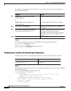
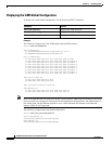
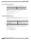
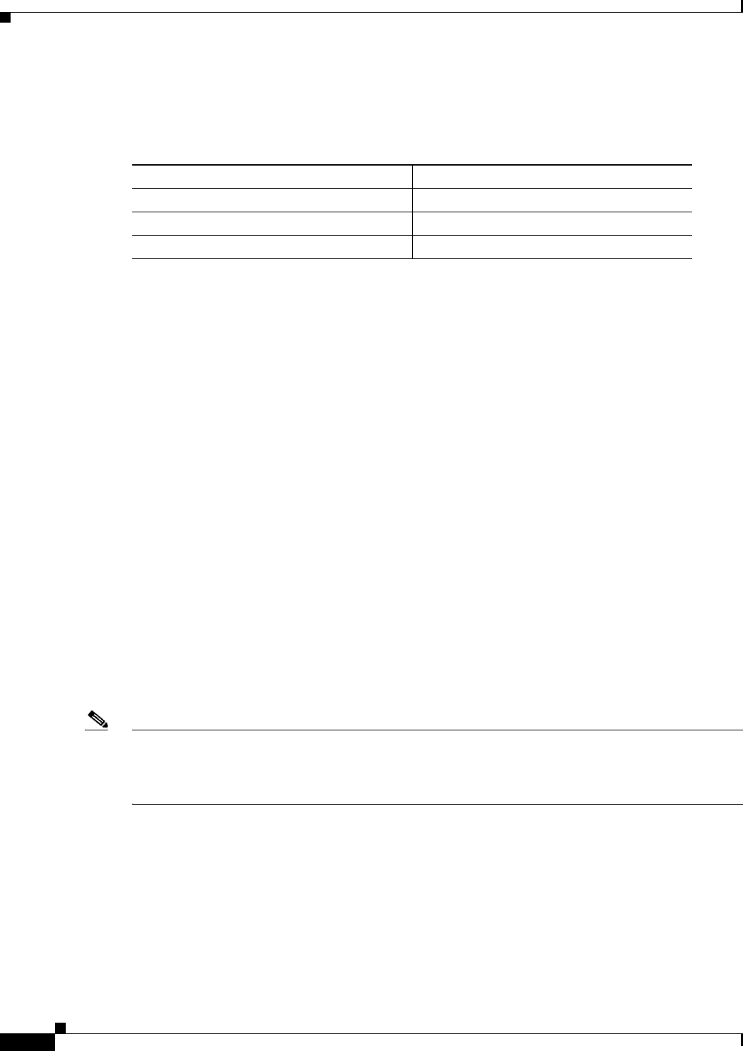
To display the switch ILMI configuration, use the following EXEC commands:
Examples
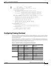
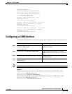
The following example shows the ATM address and the LECS address:
Switch# show atm addresses
Switch Address(es):
47.00918100000000000CA79E01.00000CA79E01.00 active
88.888888880000000000000000.000000005151.00
Soft VC Address(es):
47.0091.8100.0000.0000.0ca7.9e01.4000.0c81.0000.00 ATM0
47.0091.8100.0000.0000.0ca7.9e01.4000.0c81.8000.00 ATM3/0/0
47.0091.8100.0000.0000.0ca7.9e01.4000.0c81.8010.00 ATM3/0/1
47.0091.8100.0000.0000.0ca7.9e01.4000.0c81.8020.00 ATM3/0/2
47.0091.8100.0000.0000.0ca7.9e01.4000.0c81.8030.00 ATM3/0/3
47.0091.8100.0000.0000.0ca7.9e01.4000.0c81.9000.00 ATM3/1/0
47.0091.8100.0000.0000.0ca7.9e01.4000.0c81.9010.00 ATM3/1/1
47.0091.8100.0000.0000.0ca7.9e01.4000.0c81.9020.00 ATM3/1/2
47.0091.8100.0000.0000.0ca7.9e01.4000.0c81.9030.00 ATM3/1/3
ILMI Switch Prefix(es):
47.0091.8100.0000.0000.0ca7.9e01
88.8888.8888.0000.0000.0000.0000
ILMI Configured Interface Prefix(es):
LECS Address(es):
47.0091.8100.0000.0000.0ca7.9e01.4000.0c81.9030.01
47.0091.8100.0000.0000.0ca7.9e01.4000.0c81.9030.02
Note Since Cisco IOS Release12.0(1a)W5(5b) of the system software, addressing the interface on the route
processor (CPU) has changed for Catalyst 8510 and LightStream 1010 platforms. The ATM interface is
now called atm0, and the Ethernet interface is now called ethernet0. Old formats (atm 2/0/0 and
ethernet 2/0/0) are still supported.
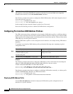
The following example shows the ILMI configuration:
Switch# show atm ilmi-configuration
Switch ATM Address (s) :
1122334455667788990112233445566778899000
LECS Address (s):
1122334455667788990011223344556677889900
Command Purpose
show atm addresses Displays the ATM addresses.
show atm ilmi-configuration Displays the ILMI configuration.
show atm ilmi-status Displays the ILMI status.