


2-7
ATM Switch Router Software Configuration Guide
OL-7396-01
Chapter 2 Understanding the User Interface
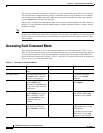
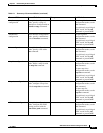
Accessing Each Command Mode
You can specify either the terminal, nonvolatile memory (NVRAM), or a file stored on a network server
as the source of configuration commands. For more information, see Chapter 26, “Managing
Configuration Files, System Images, and Functional Images.” The default is to enter commands from the
terminal console.
As a shortcut for accessing the terminal method of configuration, enter the following:
Switch# configure terminal
Enter configuration commands, one per line. End with CNTL/Z.
Switch(config)#
To exit global configuration command mode and return to privileged EXEC mode, use the exit or end
command, or press Ctrl-Z:
Switch(config)# end
Switch#
Interface Configuration Mode
Interface configuration mode provides access to commands that apply on a per-interface basis. These
commands modify the operation of an interface such as an ATM, Ethernet, or asynchronous port.
To enter interface configuration mode from global configuration mode, use the interface command with
a keyword indicating the interface type, followed by an interface number; the prompt changes to the
ATM switch router’s hostname followed by (config-if)#:
Switch(config)# interface atm 3/0/0
Switch(config-if)#
To exit interface configuration mode and return to global configuration mode, use the exit command:
Switch(config-if)# exit
Switch(config)#
To exit interface configuration mode and return to privileged EXEC mode, use the end command or press
Ctrl-Z:
Switch(config-if)# end
Switch#
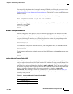
Interface Addressing Formats (Catalyst 8540)
In the ATM switch router chassis, you specify interfaces in slots 0 through 3 and 9 through 12 using the
card/subcard/port format. Slots 4 and 8 each contain a CPU (multiservice route processor). Because the
configurations on the primary and secondary route processors are automatically synchronized, they are
configured via a single network interface, specified as atm0 or ethernet0. There is no need to configure
the secondary separately from the primary, but some show commands allow you to display information
about the secondary route processor; in these cases, you specify the interface as atm-sec0 or
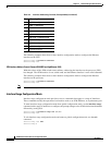
ethernet-sec0. Slots 5 through 7 contain the switch processors, which have no interfaces. Table 2-3
summarizes this addressing scheme, assuming that slot 4 is the primary route processor and slot 8 is the
secondary route processor.
Table 2-3 Interface Addressing Formats (Catalyst 8540)
Slot Addressing Format
0 card/subcard/port
1 card/subcard/port
2 card/subcard/port