


20-18
ATM Switch Router Software Configuration Guide
OL-7396-01
Chapter20 Configuring Frame Relay to ATM Interworking Port Adapter Interfaces
Configuring Frame Relay to ATM Resource Management
Example
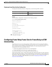
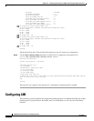
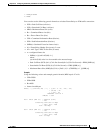
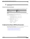
The following example displays the LMI statistics of a Frame Relay port adapter with an NNI interface:
Switch> show frame-relay lmi interface serial 0/1/0:5
LMI Statistics for interface serial 0/1/0:5 (Frame Relay NNI) LMI Type = Cisco
Invalid Unnumberred info 0Invalid Prot Disc 0
Invalid dummy Call Ref 0Invalid msg Type 0
Invalid Status Message 0Invalid Lock Shift 0
Invalid Information ID 0Invalid Report IE Len 0
Invalid Report Request 0Invalid Keep IE Len 0
Num Status Enq. Rcvd 11Num Status msgs Sent 11
Num Update Status Rcvd 0Num St Enq Timeouts 0
Num Status Enq. Sent 10Num Status msgs Rcvd 10
Num Update Status Sent 0Num Status Timeouts 0
Configuring Frame Relay to ATM Resource Management
This section describes the following resource management tasks specifically for your Frame Relay to
ATM interworking network needs:
• Configuring Frame Relay to ATM Connection Traffic Table Rows, page 20-18
• Creating a Frame Relay to ATM CTT Row, page 20-21
• Configuring the Interface Resource Management Tasks, page 20-22
For information about how to configure your ATM Connection Traffic Table rows, see Chapter 9,
“Configuring Resource Management.”
Configuring Frame Relay to ATM Connection Traffic Table Rows
A row in the Frame Relay to ATM Connection Traffic Table (CTT) must be created for each unique
combination of Frame Relay traffic parameters. All Frame Relay to ATM interworking virtual
connections then provide traffic parameters for each row in the table per flow (receive and transmit).
Multiple virtual connections can refer to the same traffic table row.
The Frame Relay traffic parameters (specified in the command used to create the row) are converted into
equivalent ATM traffic parameters. Both parameters are stored internally and used for interworking
virtual connections.
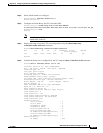
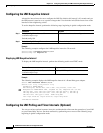
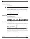
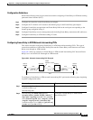
The formula used for Frame Relay to ATM traffic conversions are specified in the B-ICI specification,
V2.0. Use a frame size (n) of 250 bytes and a header size of 2 bytes. See Table 20-1.
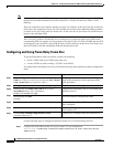
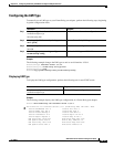
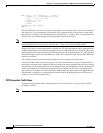
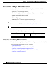
Command Purpose
show frame-relay lmi interface serial
card/subcard/port:cgn
Displays LMI statistics.
Table 20-1 Frame Relay to ATM Traffic Conversion
Peak Cell Rate (0+1) (Cells Per Second) = Peak Information Rate
1
/8 * (6/260)
Sustainable Cell Rate (0) (Cells Per Second) = Committed Information Rate
1
/8 * (6/250)
Maximum Burst Size (0) (Cells) = (Committed Burst Size
2
/8 * (1/(1-Committed
I n f o r m a t i o n R a t e /P e a k I n f o r m a t i o n R a t e ) ) + 1 ) * ( 6 / 2 5 0 )