


16-40
ATM Switch Router Software Configuration Guide
OL-7396-01
Chapter 16 Configuring Tag Switching and MPLS
MPLS VPNs
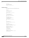
The following example shows how to configure the RFC1483 MPLS VPN interface connected to the
customer equipment from the PE ATM switch router and cross connected to the enhanced ATM router
module interface:
8540-ATM-PE1# configure terminal
8540-ATM-PE1(conf)# interface ATM11/0/2
8540-ATM-PE1#
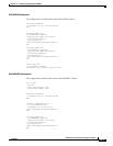
The following example shows how to configure the RFC 1483 MPLS VPN interface connected to the
provider switch from the PE ATM switch router and cross connected to the enhanced ATM router module
interface:
8540-ATM-PE1(config)# interface ATM11/0/1
8540-ATM-PE1(conf-if)# ip unnumbered Loopback0
8540-ATM-PE1(conf-if)# tag-switching ip
8540-ATM-PE1(conf-if)# mpls-forwarding interface ATM2/0/0
8540-ATM-PE1(conf-if)# end
8540-ATM-PE1#
Network Configuration Example
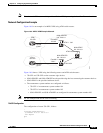
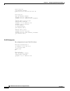
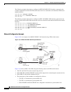
Figure 16-9 is an example of an MPLS VPN RFC 1483 network using ATM switch routers.
Figure 16-9 MPLS VPN ATM 1483 Example Network
Figure 16-9 shows an RFC 1483 VPN using the following routers and ATM switch routers:
• 75k-CE1 and 75k-CE2 are the customer edge devices.
• 8540-ATM-PE1 and 8540-ATM-PE2 are the provider edge devices connecting the customer devices.
• 8540-ATM-P is the provider backbone device.
• The autonomous system numbers are configured as follows:
–
75k-CE1 is in autonomous system number 104
–
75k-CE2 is in autonomous system number 105
–
8540-ATM-PE1 and 8540-ATM-PE2 are configured in autonomous system number 100
VPN 1
75k-CE1
VPN 1
75k-CE2
8540-ATM-PE1
lo0 - 22.0.0.1
ATM 11/0/2
PVC 2 100
8540-ATM-P
lo0 - 23.0.0.1
ATM 0/0.2
12.0.0.1
PVC 30 3 300
ATM 2/0.2
7.0.0.2
PVC 2 2 100
8540-ATM-PE2
lo0 - 24.0.0.1
ATM 11/0/1
PVC 0 32
ATM 12/0/0
PVC 0 32
ATM 12/0/2
PVC 0 32
ATM 12/0/2
PVC 0 32
ATM 12/0/1
PVC 2 100
73380