


19-39
ATM Switch Router Software Configuration Guide
OL-7396-01
Chapter 19 Configuring Circuit Emulation Services
Configuring T1/E1 Structured (n x 64) Circuit Emulation Services
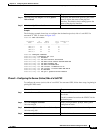
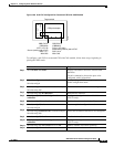
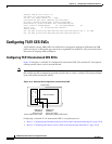
Assume that certain configuration information has already been established for a soft PVC (see
Figure 19-6) and that you are to create an additional soft PVC involving the same CES module.
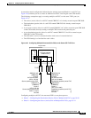
The following assumptions apply to creating multiple soft PVCs on the same T1/E1 port (see
Figure 19-7):
• The source (active) side of a soft PVC named CBR-PVC-A is already created on port CBR 3/0/0.
• The destination (passive) side of a soft PVC named CBR-PVC-B is already created on port
CBR 3/0/3.
• A new source (active) side of a soft PVC named CBR-PVC-AC will be created on port CBR 3/0/0
of the CES module, thereby creating a multiple CES circuit on this particular port.
• A new destination (passive) side of a soft PVC named CBR-PVC-CA will be created on port
CBR 3/0/2 of the CES module.
• The CES AAL1 service is structured and the clock source is network-derived.
• The CES framing is esf and the line code is b8zs.
Figure 19-7 Configuring Multiple Structured Soft PVCs on the Same CES T1/E1 Port
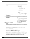
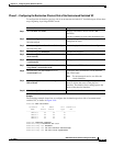
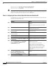
Configuring multiple soft PVCs for structured CES is a two-phase process:
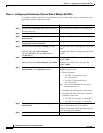
• Phase 1—Configuring the Destination (Passive) Side of Multiple Soft PVCs, page 19-40
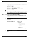
• Phase 2—Configuring the Source (Active) Side of Multiple Soft PVCs, page 19-41
CES port adapter
(module slot 1)
Target switch
27208
CBR-PVC-A
(CBR3/0/0)
Circuit 1
(VPI 0, VCI 16)
Source (active) end of PVC
DSO 1-3, and 7
No CAS
CBR-PVC-B
(CBR3/0/3)
Circuit 1
(VPI 0, VCI 1040)
Destination (passive) end of PVC
DSO 10-13
No CAS
0
123
T1/E1
CBR-PVC-AC
(CBR3/0/0)
Circuit 2
24 DS0 time slots
(VPI 0, VCI 32)
Source (active) end of PVC
CBR-PVC-CA
(CBR3/0/2)
Circuit 2
24 DS0 time slots
(VPI 0, VCI 2064)
Destination (passive) end of PVC
S
w
i
t
c
h
i
n
g
F
a
b
r
i
c